


3
SPECIFICATIONS
Power Output KS-AX5700: 200 W RMS x 2 channels at 4 Ω and ≤ 1% THD + N
KS-AX5500: 100 W RMS x 4 channels at 4 Ω and ≤ 1% THD + N
Signal-to-Noise Ratio 80 dBA (reference: 1 W into 4 Ω)
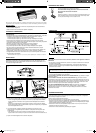
TROUBLESHOOTING
For more details, consult your “JVC IN-CAR ENTERTAINMENT” car audio dealer.
The POWER/PROTECTOR lamp does not light.
• Confi rm if the fuse is blown.
• Confi rm if the ground lead is connected securely to a metal part of the car.
• Make sure that the equipment connected to this unit is turned on.
• Use a relay if your system employs too many amplifi ers.
• Confi rm the battery voltage (11 V to 16 V).
The POWER/PROTECTOR lamp lights in red and/or the unit heats up abnormally.
• Confi rm if the impedance of the connected speaker is suitable.
• Confi rm if the speaker wirings are short-circuited.
• Leave the unit turned off for a while as it cools down.
No sound is heard.
• Confi rm if the POWER/PROTECTOR lamp lights in green (see “POWER SUPPLY” on page 1).
• Is the remote turn-on line lead connected correctly?
• Are RCA pin cords connected to the INPUT jacks?
• Is the speaker input connector from the receiver connected to the HIGH INPUT terminal?
• Is this amplifi er grounded?
Alternator noise is heard.
• Keep the power connecting leads away from the RCA pin cords.
• Keep the RCA pin cords away from other electrical cables in the car.
• Confi rm if the ground lead is connected securely to a metal part of the car.
• Confi rm if the negative speaker leads are touching the car chassis.
• Confi rm if the noise originates in the receiver.
• Replace the plugs or use plugs with load resistors.
• Connect a bypass capacitor across the accessory switches (horn, fan, etc.).
Noise when connected to AM (MW/LW) tuner.
• Move the speaker and power leads away from the antenna (aerial) lead.
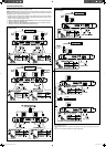
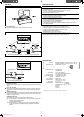
CONTROLS
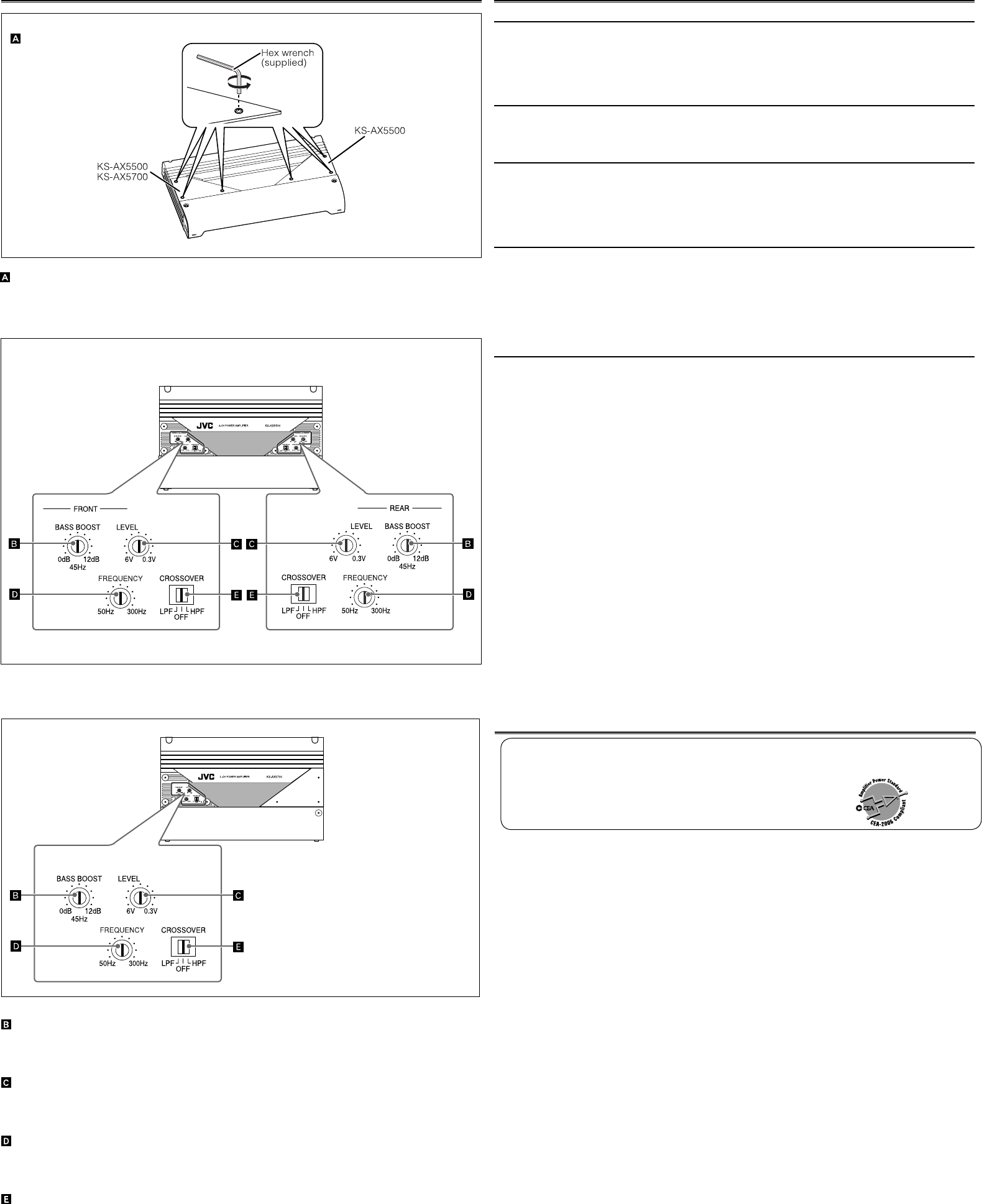
KS-AX5700
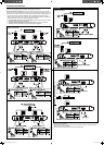
Control Panel cover
To operate the following controls, remove the bolts with a hex wrench
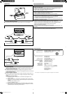
BASS BOOST controller
Turning this enables boosting of the 45 Hz frequency within a range of 0 dB to +12 dB. Adjust
the level while listening to the sound. This control is preset to the middle of this range at the
factory.
Input LEVEL controller
The input level can be adjusted with this control when this unit is connected to other source
equipments. Turn it in the clockwise direction when the output level of the car audio seems
low.
FREQUENCY controller
Turning this enables adjustment of the frequency cut-off point through the fi lter within a range
of 50 Hz to 300 Hz. Adjust the level while listening to the sound. This control is preset to the
middle of this range at the factory.
CROSSOVER fi lter switch
OFF: Normally, set to this position. (Preset to this position at the factory.)
LPF: Set to this position when you want to turn on the LPF (Low-pass fi lter) switch. You can
use the following terminals for a subwoofer system.
KS-AX5500: REAR SPEAKER OUTPUT
KS-AX5700: SPEAKER OUTPUT
HPF: Set to this position when you want to turn on the HPF (High-pass fi lter) switch. The
low frequency signals are not applied to the left/right speaker when a subwoofer is
connected.
KS-AX5500
Maximum Power Output KS-AX5700: 900 W
KS-AX5500: 800 W
Load Impedance 4 Ω (2 Ω to 8 Ω allowance)
4 Ω (4 Ω to 8 Ω allowance) (Bridge mode)
Frequency Response 5 Hz to 50,000 Hz ( +0, –3 dB)
Input Sensitivity/Impedance 1 V/20 kΩ (0.3 V to 6 V, variable)
Distortion Less than 0.04% (at 1 kHz)
Power Requirement DC 14.4 V (11 V to 16 V allowance)
Grounding system Negative ground
Dimensions (W/H/D) 400 mm × 264 mm × 63 mm
(15-
3
/4 in.
×
10-
7
/16 in.
×
2-
1
/2 in.)
Mass (approx.) 5.7 kg (12.6 lbs.)
Supplied Accessories Speaker input connector × 2 (KS-AX5500)
× 1 (KS-AX5700)
Mounting Screw (φ 4.0 × 20 mm (
13
/16 in.)
) × 4
Terminal cover × 1
Hex bolt × 2
Hex wrench × 1
Design and specifi cations are subject to change without notice.
EN_KS-AX5500&5700[J_E_U]f.indd 3EN_KS-AX5500&5700[J_E_U]f.indd 3 05.6.30 8:43:16 PM05.6.30 8:43:16 PM