


3
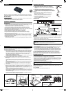
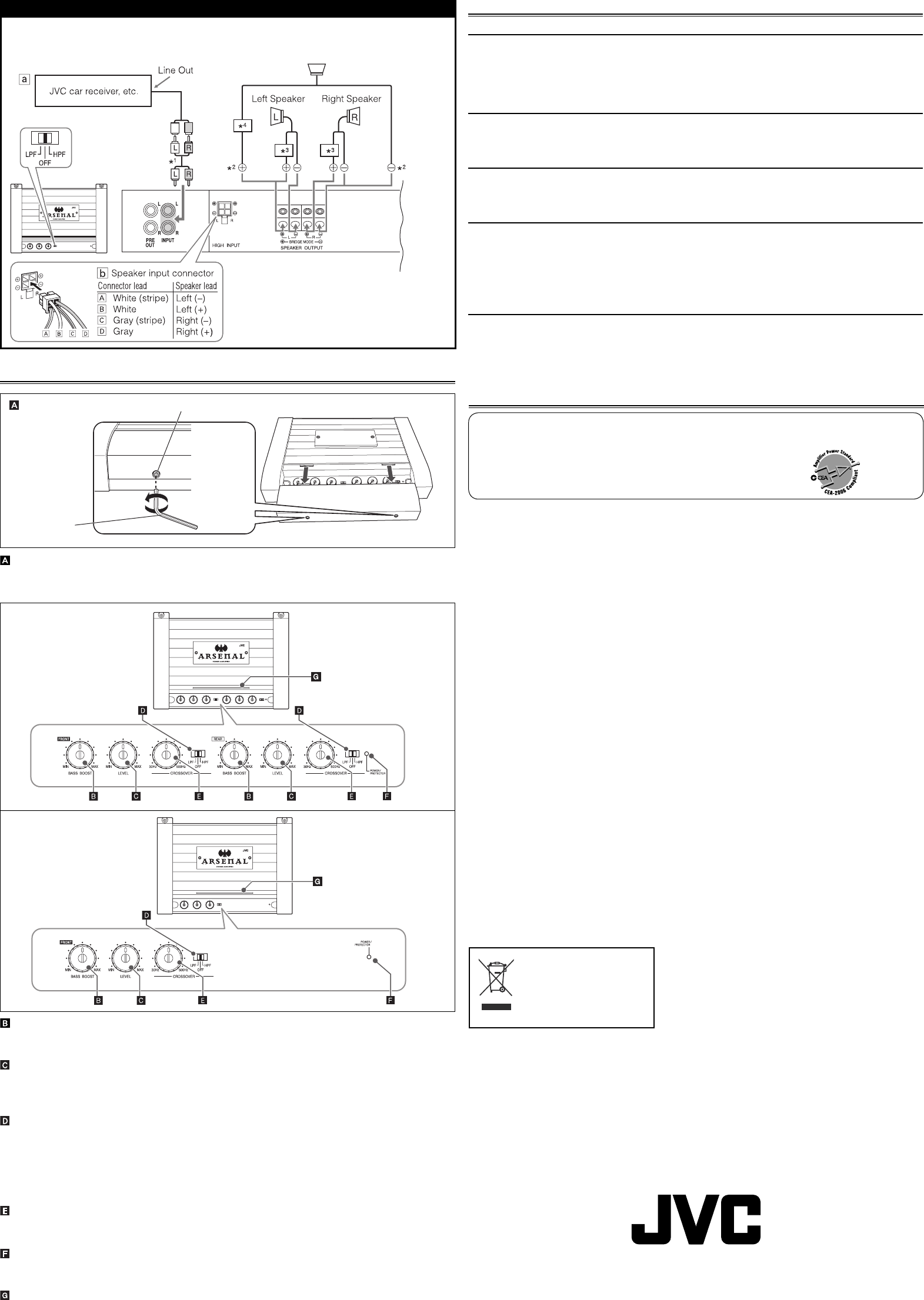
BASS BOOST controller
Turning this boosts the 45 Hz frequency within the range of 0 dB to +18 dB. Adjust the level
while listening to the sound. This control is preset to MIN when the unit is shipped.
Input LEVEL controller
The input level can be adjusted with this control when this unit is connected to other source
equipment. Adjust the level while listening to the sound. This control is preset to MIN when
the unit is shipped.
CROSSOVER fi lter switch
OFF: Normally, set to this position. The switch is preset to this position when the unit is
shipped.
LPF: Set to this position when you want to turn on the LPF (Low-Pass Filter) switch (the
Low-Pass Filter transmits frequencies lower than the cutoff frequency).
HPF: Set to this position when you want to turn on the HPF (High-Pass Filter) switch (the
High-Pass Filter transmits frequencies higher than the cutoff frequency).
CROSSOVER frequency controller
Turning this adjusts the cutoff frequency within the range of 30 Hz to 500 Hz. Adjust the level
while listening to the sound. This control is preset to 30 Hz when the unit is shipped.
POWER/PROTECTOR lamp
The lamp lights in green while the unit is turned on. When the lamp does not light or lights in
red with the unit on, it indicates there may be any trouble (see "TROUBLESHOOTING").
Power lndicator
The blue lamp illuminates while the unit is turned on.
Maximum Power Output 800 W
Load Impedance 4 Ω (2 Ω to 8 Ω allowance)
4 Ω (4 Ω to 8 Ω allowance) (Bridge Mode)
Frequency Response 5 Hz to 50 kHz* ( +0, –3 dB)
* Subsonic fi lter cuts off extremely low frequency signals less than
20 Hz.
Input Sensitivity/Impedance 2 V/45 kΩ (0.3 V to 6 V, variable)
Distortion Less than 0.04% (at 1 kHz)
Power Requirement DC 14.4 V (11 V to 16 V allowance)
Grounding system Negative ground
Dimensions (W×H×D)
15-
3
/4 inch
×
2-
3
/8 inch
×
11-
3
/8 inch
(
400 mm × 60 mm × 288 mm
)
Mass (approx.) KS-AR7004: 11.7 lbs. (5.3 kg)
KS-AR7002: 11.5 lbs. (5.2 kg)
Accessories Speaker input connector
KS-AR7004: 4P × 2
KS-AR7002: 4P × 1
Screw (Dia.
3
/16 inch (4 mm) ×
13
/16 inch
(20 mm
)
) × 4
Hex wrench
4 mm × 1
3 mm × 1
Spacer × 6
Bracket
L × 1
S × 2
Screw (M4 ×
1
/2 inch
(12 mm
)
) × 6
Washer (M4) × 6
Spring Lock Washer (M4) × 6
Design and specifi cations are subject to change without notice.
TROUBLESHOOTING
For more details, consult your JVC car audio dealer.
The POWER/PROTECTOR lamp does not light.
• Change the fuses if the current one is blown.
• Connect the ground lead securely to a metal part of the car.
• Turn on the equipment connected to this unit.
• Use a relay if your system employs too many amplifi ers.
• Confi rm the battery voltage (11 V to 16 V).
The POWER/PROTECTOR lamp lights in red and/or the unit heats up abnormally.
• Use the speakers of suitable impedance.
• Correct the speaker wirings if they are short-circuited.
• Leave the unit turned off for a while to cool it down.
No sound is heard.
• Confi rm the connections for power supply (see “POWER SUPPLY” on page 1).
• Connect RCA pin cords to the INPUT jacks, or the speaker input connector to the HIGH INPUT
terminal.
Alternator noise is heard.
• Keep the power cords away from the RCA pin cords.
• Keep the RCA pin cords away from other electrical cables in the car.
• Connect the ground lead securely to a metal part of the car.
• Make sure the negative speaker leads do not touch the car chassis.
• Replace the plugs or use plugs with load resistors.
• Connect a bypass capacitor across the accessory switches (horn, fan, etc.).
Noise is made when you connect the unit to an AM tuner.
• Move the speaker and power cords away from the antenna lead.
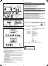
CONTROLS
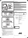
Control cover
To operate the following controls, remove the hex screws with a provided hex wrench (3 mm)
and detach the control cover. Attach it again after your operation.
KS-AR7004
KS-AR7002
Hex screw
Hex wrench
(3 mm)
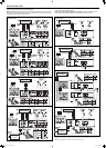
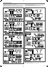
KS-AR7002
2-speaker system plus subwoofer (1 amplifi er)
*
1
Not provided for this unit.
*
2
Bridge wiring
*
3
Use a High-pass crossover (not provided).
*
4
Use a Low-pass crossover (not provided).
The minimum impedance should be 4 Ω for each of left and right speakers, and the
subwoofer.
Subwoofer
SPECIFICATIONS
Power Output KS-AR7004: 100 W RMS x 4 channels at 4 Ω and ≤ 1% THD + N
KS-AR7002: 150 W RMS x 2 channels at 4 Ω and ≤ 1% THD + N
Signal-to-Noise Ratio 80 dBA (reference: 1 W into 4 Ω)
[European Union only]
EN, FR
© 2007 Victor Company of Japan, Limited 0207MNMMDWTKC
EN_KS-AR7004_7002[J].indd 3EN_KS-AR7004_7002[J].indd 3 07.2.20 8:19:23 PM07.2.20 8:19:23 PM