


11
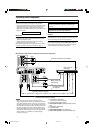
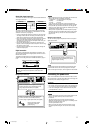
DIGITAL OUT
PCM/STREAM
DIGITAL IN
2(DBS)
1(DVR/DVD)
3(VCR)
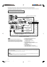
NOTES
• When shipped from the factory, the DIGITAL IN terminals have
been set for use with the following components:
– 1(DVR/DVD): For DVD recorder or DVD player
– 2(DBS): For DBS tuner
– 3(VCR): For VCR
If you connect other components, change the digital input
(DIGITAL IN) terminal setting correctly. See “Setting the digital
input (DIGITAL IN) terminals—DIGITAL IN 1/2/3” on page 22.
• Select the correct digital input mode. See “Selecting the analog
or digital input mode” on page 14.
• When you want to operate the connected component (except
DBS tuner) using the AV COMPU LINK remote control system
(see pages 34 and 35), connect them also as described on
pages 7 to 10.
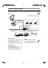
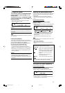
Digital connection
This receiver is equipped with three DIGITAL IN terminals—one
digital coaxial terminal and two digital optical terminals—and one
DIGITAL OUT terminal.
To reproduce the digital sound, use the digital connection in
addition to the analog connection methods described on pages 7
to 10.
Digital coaxial cable (not supplied)
Digital optical cable (not supplied)
Turn off all components before making connections.
• When you connect other components, refer also to their
manuals.
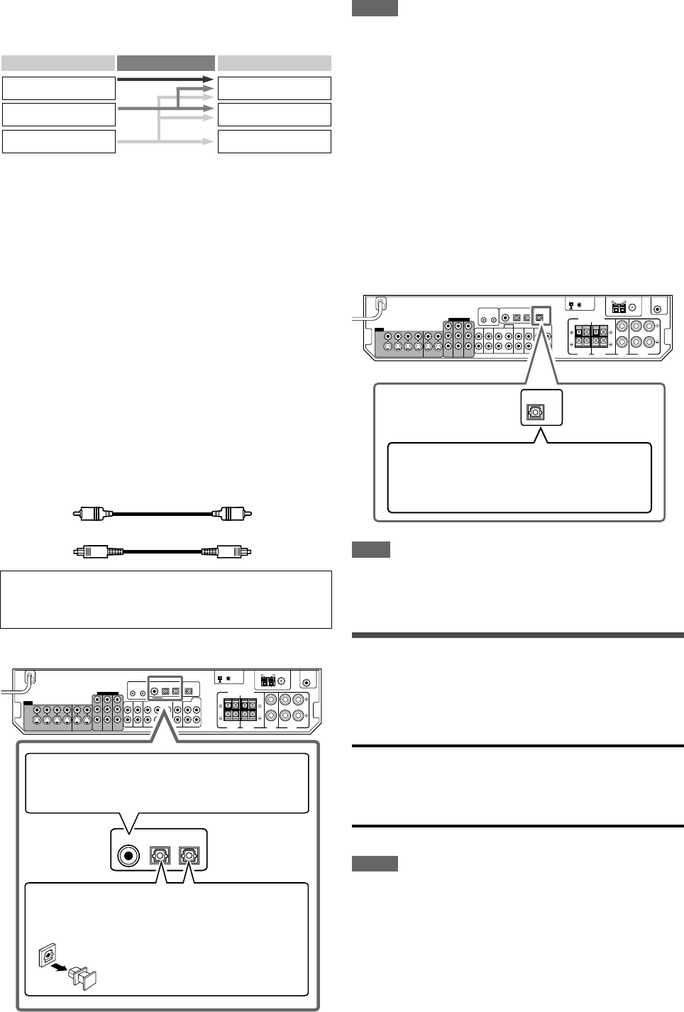
7 Digital input terminals
When the component has a digital coaxial output
terminal, connect it to the 1(DVR/DVD) terminal,
using a digital coaxial cable (not supplied).
When the component has a digital optical output
terminal, connect it to the 2(DBS) or 3(VCR)
terminal, using a digital optical cable (not supplied).
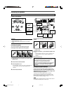
Before connecting a digital
optical cable, unplug the
protective plug.
NOTE
The digital signal format transmitted through the DIGITAL OUT
terminal is the same as that of the input signal. For example,
when the DTS signals are input, the DTS signals are transmitted.
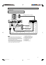
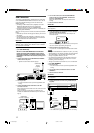
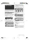
Connecting the power cord
When all the audio/video connections have been made, connect
the AC power plug to the wall outlet. Make sure that the plugs are
inserted firmly. The standby lamp lights in red.
CAUTIONS:
• Do not touch the power cord with wet hands.
• Do not alter, twist or pull the power cord, or put anything heavy
on it, which may cause fire, electric shock, or other accidents.
• If the cord is damaged, consult a dealer and have the power
cord replaced with a new one.
NOTES
•Keep the power cord away from the connecting cables and the
antenna. The power cord may cause noise or screen
interference.
• The preset settings such as preset channels and sound
adjustment may be erased in a few days in the following cases:
– When you unplug the power cord.
– When a power failure occurs.
• When you unplug the power cord with the receiver on and
connect the power cord again, the receiver enters standby
mode.
7 Digital output terminal
You can connect any digital components which have an optical
digital input terminal.
Connecting digital recording equipment to the
DIGITAL OUT terminal enables you to perform
digital-to-digital recording.
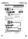
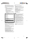
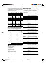
About video signal conversion
This receiver can convert video signals. See the table below about
video signal conversion.
To convert composite video and S-video signal into component
video signal, set the “DVD VIDEO IN,” “VCR VIDEO IN,” or “DBS
VIDEO IN” to “<S/C>” (see page 22).
• If using composite video cable for connecting to the video input
and using S-video cable for connecting to the video output, the
video signal is converted into S-video signal automatically.
•Even if the recording components are connected to the receiver
using the S-video cords and the playpack components are
connected to the receiver using the composite video cords, you
can record the picture on TV.
• Pictures may be distorted if the signals are converted. If this
happens, connect the playback source component and TV using
the cords of the same type.
• Incoming signal of component can be emitted only through the
component output jacks.
Video Input Converted Video Output
Component
S-video
Video (composite)
Component
S-video
Video (composite)
11-13D301J2.p65 05.6.20, 4:35 PM11