


4
~
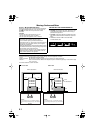
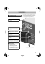
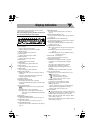
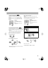
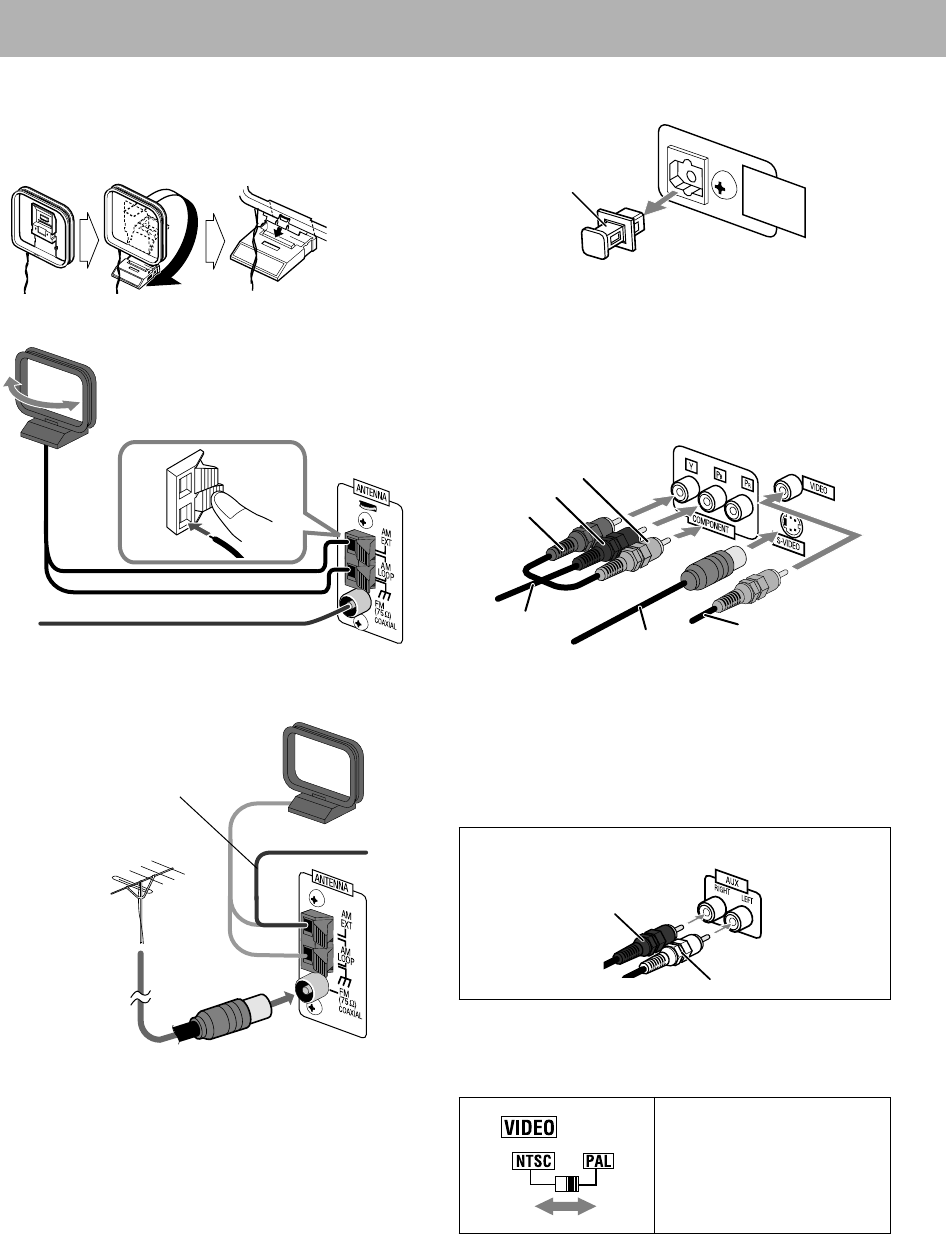
AM/FM antenna
To assemble the AM loop antenna
To connect AM/FM antenna
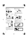
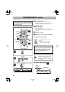
For better AM/FM reception
• Disconnect the supplied FM antenna, and connect to an
outdoor FM antenna using a 75
Ω
wire with coaxial type
connector (IEC or DIN45325).
• Make sure the antenna conductors do not touch any other
terminals, connecting cords and power cord. Also, keep the
antennas away from metallic parts of the System,
connecting cords, and the AC power cord. This could cause
poor reception.
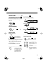
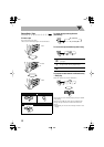
Ÿ
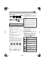
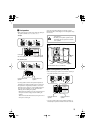
Digital audio component
• Set “DIGITAL AUDIO OUTPUT” in the “AUDIO”
preference display correctly according to the connected
digital audio equipment (see page 37). If setting is incorrect,
loud noise may be generated causing damage to the
speakers.
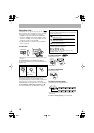
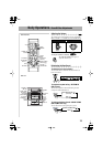
!
TV/monitor
• To select progressive scanning mode, use COMPONENT
jacks (MX-JE5 only).
• Connect the VIDEO jack, S-VIDEO jack, or
COMPONENT jacks (MX-JE5 only) whichever you
want to use.
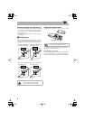
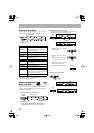
To set the video output selector
You can select the video output to match it to the color
system of your TV.
Extend it so that you can obtain the best
reception.
AM loop antenna
(supplied)
FM antenna (supplied)
Turn it until the best
reception is obtained.
AM loop antenna (supplied)
Keep it connected.
Vinyl-covered wire (not supplied)
Extend it horizontally.
FM outdoor antenna
(not supplied)
When connecting the auxiliary equipment (AUX)
NTSC:
For an NTSC TV.
PAL:
For a PAL TV.
For a multi-color TV, you can
select either one.
OPTICAL
DIGITAL
OUTPUT
Protective cap
Green
Blue
Red
Composite video
cord (supplied)
S video cord
(not supplied)
Component
video cord
(not supplied)
Red
White
Stereo audio cord
(not supplied)