


– 7 –
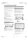
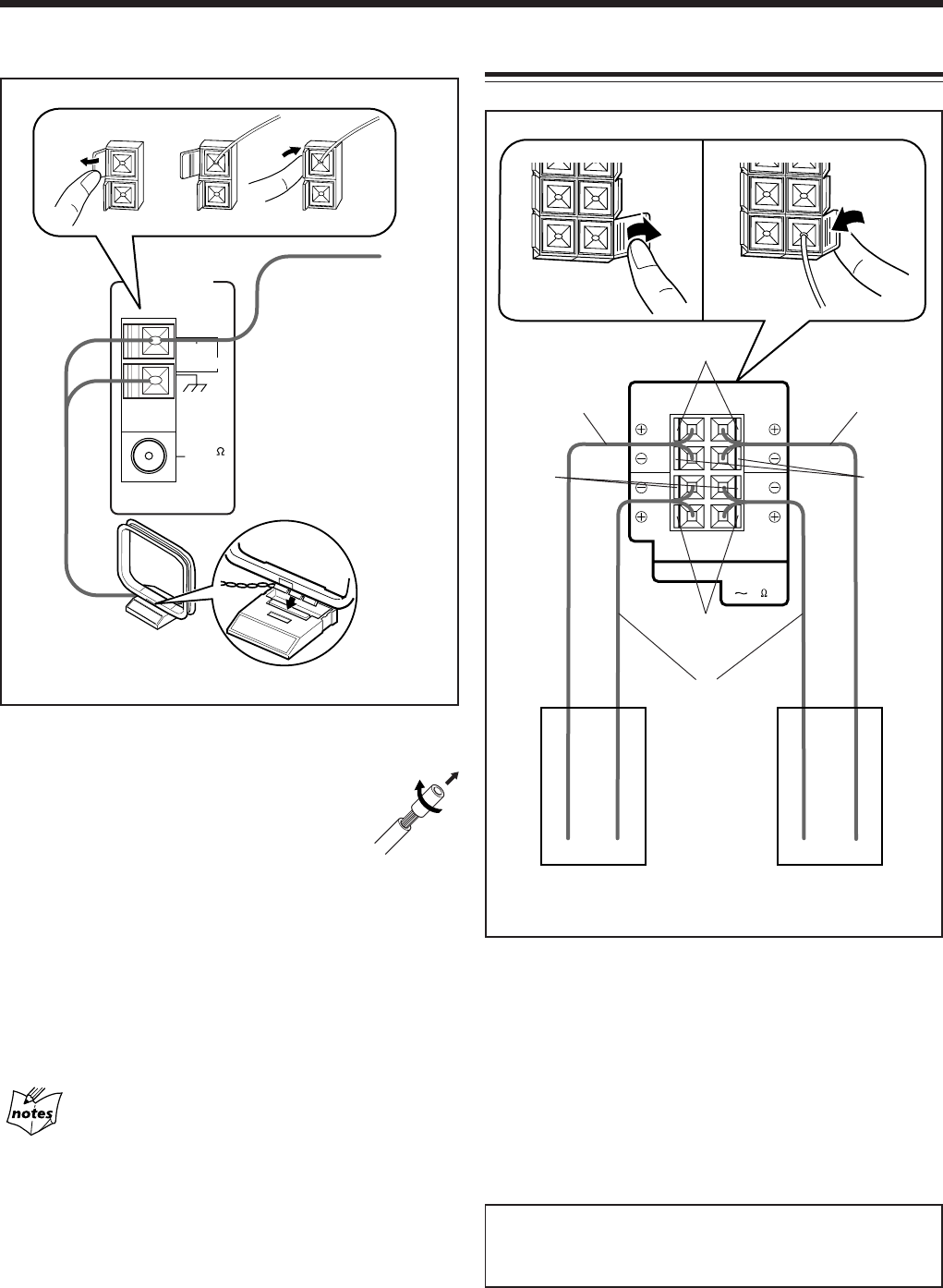
1
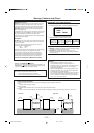
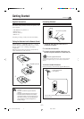
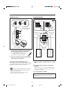
Connect the AM (MW/LW) loop antenna to
the AM LOOP terminals as illustrated.
• If the AM (MW/LW) loop antenna wire
is covered with vinyl, remove the vinyl
by twisting it as shown in the diagram.
2 Turn the AM (MW/LW) loop antenna until
you have the best reception.
To connect an outdoor AM (MW/LW) antenna
When reception is poor, connect a single vinyl-covered wire
to the AM EXT terminal and extend it horizontally. The AM
(MW/LW) loop antenna must remain connected.
For better reception of both FM and AM (MW/LW)
• Make sure the antenna conductors do not touch any other
terminals and connecting cords.
• Keep the antennas away from metallic parts of the unit,
connecting cords, and the AC power cord.
AM (MW/LW) antenna
Vinyl-covered wire
(not supplied)
AM (MW/LW) loop
antenna (supplied)
COAXIAL
ANTENNA
AM LOOP
FM 75
AM EXT
1
2
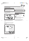
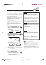
Connecting Speakers
SUBWOOFERS
MAIN
SPEAKERS
CAUTION: SPEAKER
IMPEDANCE
616
LEFT
LEFT
RIGHT
RIGHT
Blue
1
3
Black
Red
Speaker cords
(blue/black)
Right speaker Left speaker
Speaker cords
(red/black)
Speaker cords
(red/black)
Black
2
1
Open the speaker terminals on the rear of the
unit.
2 Insert the end of the speaker cord into the
terminal.
Match the polarity (colors) of the speaker terminals: Red
(+) to red (+) and black (–) to black (–); Blue (+) to blue
(+) and black (–) to black (–).
3 Close the speaker terminals.
IMPORTANT: Use only speakers with the same speaker
impedance as indicated by the speaker terminals on the
rear of the unit.
EN01-14.CA-MXGT91R&G71R[B]f 2/26/01, 6:56 PM7