


5
Getting Started
EnglishEnglishEnglishEnglishEnglishEnglishEnglish
LVT0686-009B / CA-K1R/CA-K3R(B) / English
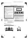
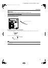
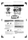
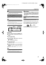
Connecting the AM (MW/LW) Antenna
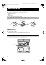
Rear Panel of the Unit
• Even when connecting an outside AM (MW/LW) antenna, keep the indoor AM (MW/LW) loop connected.
CAUTION:
• To avoid noise, keep antennas away from the System, the connecting cord and the AC power cord.
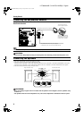
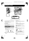
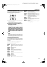
Connecting the Speakers
1. Open each of the terminals to connect the speaker wire leads.
2. Connect the speaker cords to the Speaker terminals of the Unit.
Connect the red (+) and black (–) wires of the right side speaker to the red (+) and black (–) terminals marked RIGHT on the System.
Connect the red (+) and black (–) wires of the left side speaker to the red (+) and black (–) terminals marked LEFT on the System.
3. Close each of the terminals to securely connect the cords.
CAUTIONS:
• A TV may display irregular colors if located near the speakers. If this happens, set the speakers away
from the TV.
• Use speakers with the correct impedance only. The correct impedance is indicated on the rear panel.
ANTENNA
AM
LOOP
AM
EXT
GND
LEFT
RIGHT
AUX IN ANTENNA
AM
LOOP
AM
EXT
FM75
COAXIAL
GND
LEFT
CAUTION:
SPEAKER IMPEDANCE 6 16 OHMS.
SPEAKERS
RIGHT
FM 75
COAXIAL
AM (MW/LW) loop antenna (Supplied)
Turn the loop until you
have the best reception.
Attach the AM (MW/LW)
loop to its base by snap-
ping the tabs on the loop
into the slot in the base.
AM (MW/LW) antenna wire (not supplied)
If reception is poor, connect the outside antenna.
LEFT
CAUTION:
SPEAKER IMPEDANCE 6 16 OHMS.
SPEAKERS
RIGHT
Right side (rear view) Left side (rear view)
Black
Black
Red
Red
MX-K1R&MX-K3R(B).book Page 5 Friday, March 23, 2001 9:49 AM