


7
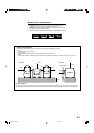
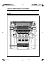
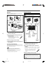
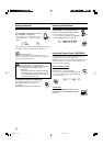
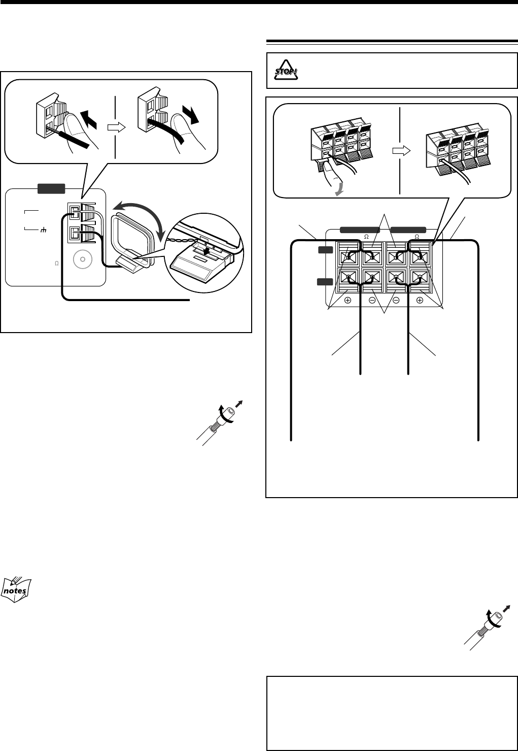
MAIN SPEAKER
SUB-WOOFER
6–16 6–16
RIGHT
LEFT
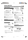
1
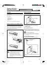
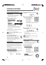
Press and hold the clamp of the AM terminal
on the rear of the unit.
2
Insert the end of the AM loop antenna cord
into the terminal.
• If the AM loop antenna wire is covered
with vinyl, remove the vinyl by twisting it
as shown in the diagram.
3
Release the finger from the clamp.
4
Turn the AM loop antenna until you have the
best reception.
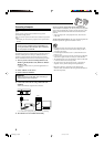
To connect an outdoor AM antenna
When reception is poor, connect a single vinyl-covered wire
to the AM terminal and extend it horizontally. (The AM loop
antenna must remain connected.)
For better reception of both FM and AM
• Make sure the antenna conductors do not touch any other
terminals and connecting cords.
•Keep the antennas away from metallic parts of the unit,
connecting cords, and the AC power cord.
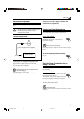
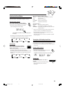
1
Press and hold the clamp of the speaker
terminal on the rear of the unit.
2
Insert the end of the speaker cord into the
terminal.
Match the colors (polarity): Blue (+) to blue (+) and black
(–) to black (–); red (+) to red (+) and black (–) to black
(–).
• If the wire is covered with vinyl, remove
the vinyl by twisting it as shown in the
diagram.
3
Release the finger from the clamp.
IMPORTANT:
• Use only speakers with the same speaker impedance as
indicated by the speaker terminals on the rear of the
unit.
• DO NOT connect more than one speaker to one speaker
terminal.
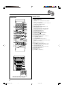
AM antenna
Make sure to connect the wire correctly: The white end to
AM EXT, the black end to GND.
Vinyl-covered wire
(not supplied)
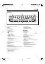
Connecting Speakers
Speaker
cord
(red/black)
From left
main
speaker’s
terminals
Speaker cord
(red/black)
Speaker cord
(blue/black)
From right
main
speaker’s
terminals
From left
subwoofer’s
terminals
From right
subwoofer’s
terminals
1, 2
Speaker cord
(blue/black)
Blue
Red
Black
AM
LOOP
FM coaxial
GND
AM EXT
(75 )
ANTENNA
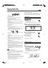
1, 2
DO NOT carry the speaker by holding the tube
duct (on the top of the speaker).
Black
3
3
4
AM loop antenna
(supplied)
MXGC5[A]_01-09.p65 05.4.13, 5:11 PM7