


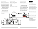
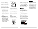
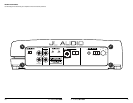

AMPLIFIER CONTROLS
1) “Input Sens.”: Once the appropriate “Input
Voltage” range has been selected, the control
labeled “Input Sens.” located in the “Amplifier
Controls” section can be used to match the
source unit’s output voltage to the input
stage of the amplifier for maximum clean
output. Rotating the control clockwise will
result in higher sensitivity (louder for a given
input voltage). Rotating the control counter-
clockwise will result in lower sensitivity
(quieter for a given input voltage.)
Bass Boost Controls
Input Voltage
Low
|
High
CH 1 (Left)
Input Sens. LP Filter
Filter Freq. (Hz)
40
45
55
65
80
100
200
Bass Boost
Remote
Bass Port
PowerProtect
CH 2 (Right)
Pre-Outs
To properly set the amplifier for maximum
clean output, please refer to Appendix A (page
12
) in this manual. After using this procedure,
you can then adjust any or all “Input Sens.”
levels downward if this is required to achieve
the desired system balance.
Do not increase any “Input Sens.” setting
for any channel(s) of any amplifier in the
system beyond the maximum level established
during the procedure outlined in Appendix
A (page 12). Doing so will result in audible
distortion and possible speaker damage.
Filter Controls
Most speakers are not designed to reproduce
the full range of frequencies audible by the
human ear. For this reason, most speaker
systems are comprised of multiple speakers, each
dedicated to reproducing a specific frequency
range. Filters are used to select which frequency
range is sent to each section of a speaker system.
The division of frequency ranges to different
speakers can be done with passive filters (coils
and/or capacitors between the amplifier outputs
and the speakers), which are acceptable and
commonly used for filtering between mid-
range speakers and tweeters. Filtering between
subwoofer systems and satellite speaker systems
is best done with active filters, which cut off
frequency content at the input to the amplifier.
Active filters are more stable than passive filters
and do not introduce extraneous resistance,
which can degrade subwoofer performance.
The active filter built into the G1700 can be
used to eliminate potentially harmful and/or
undesired frequencies from making their way
through the amplifier sections to the speaker(s).
This serves to improve tonal balance and to avoid
distortion and possible speaker failure. Correct
use of these filters can substantially increase the
longevity and fidelity of your audio system.
The G1700 employs a sophisticated, variable,
low-pass active filter for its internal channel. This
feature is designed to attenuate frequencies above
its filter frequency, so that the system’s subwoofers
do not reproduce any audible midrange content.
2) Filter Operation: The low-pass filter in the
G1700 is fully variable between 40 Hz and
200 Hz via the “Filter Freq.” control knob
and features the ability to select between a
moderate “12dB” per octave or a steep “24dB”
per octave slope via the “Mode/Slope” switch.
Depending on the subwoofer system and
the vehicle, different slopes may be required
to produce a smooth transition to the mid-
bass speakers in the system. Experiment to
find the slope which best matches the acoustic
requirements of your system.
TURNON LEAD
The G1700 uses a conventional +12V remote
turn-on lead, typically controlled by the source
unit's remote turn-on output. The amplifier will
turn on when +12V is present at its “Remote”
input and turn off when +12V is switched off. If
a source unit does not have a dedicated remote
turn-on output, the amplifier’s turn-on lead can
be connected to +12V via a switch that derives
power from an ignition-switched circuit.
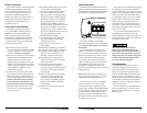
The G1700’s “Remote” turn-on connector is
designed to accept 18 AWG – 12 AWG wire. To
connect the remote turn-on wire to the amplifier,
first back out the set screw on the top of the
terminal block, using the supplied 2.5 mm hex
wrench. Strip 1/2 inch (12mm) of wire and insert
the bare wire into the terminal block, seating it
firmly so that no bare wire is exposed. While
holding the wire in the terminal, tighten the set
screw firmly, taking care not to strip the head of
the screw and making sure that the wire is firmly
gripped by the set screw.
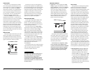
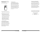
INPUT SECTION
The G1700’s input section allows you to send
signal to the amplifier section through the use
of two differential-balanced inputs, one for the
left channel signal and one for the right channel
signal. Connection is via RCA-type jacks.
Bass Boost Controls
Input Voltage
Low
|
High
CH 1 (Left)
Input Sens. LP Filter
Filter Freq. (Hz)
40
45
55
65
80
100
200
Bass Boost
Remote
Bass Port
PowerProtect
CH 2 (Right)
Pre-Outs
You may run a stereo or a mono signal into
the inputs of the amplifier. The amplifier’s input
section automatically sums stereo signals to mono
for the internal amplifier section. The amplifier
will operate with only one input connection (left
or right), but will require an increase in input
sensitivity to overcome the loss of signal. If a
mono input signal is to be run, we recommend
that you use a “Y-adaptor” to split the mono
signal into both inputs of the amplifier.
INPUT VOLTAGE RANGE:
A wide range of signal input voltages can be
accommodated by the G1700’s input section
(200mV – 8V). This wide range is split up into
two sub-ranges, accessible via a switch located to
the left of the Input Connectors.
The “Low” position on the “Input Voltage”
switch selects an input sensitivity range between
200mV and 2V. This means that the “Input
Sens.” rotary control will operate within that
voltage window. If you are using an aftermarket
source unit or an OEM interface processor with
conventional preamp-level outputs, this is most
likely the position that you will use.
The “High” position on the “Input Voltage”
switch selects an input sensitivity range between
800mV and 8V. This is useful for certain high-
output preamp level signals as well as speaker-
level output from source units and
small amplifiers.
To use speaker-level sources, splice the speaker
output wires of the source unit or small amplifier
onto a pair of RCA plugs. No line output
converter is needed in most cases.
The output of the amplifier will decrease for a
given input voltage when the “Input Range”
switch is placed in the “High” position.
Conversely, the output will be higher with the
switch in the “Low” position. While this may
sound counter-intuitive, it is consistent with the
descriptions above.
6 JL AUDIO G1700 JL AUDIO G1700 7