


The preamp output signal is not affected by the
“Bass Boost” processing selected for the amplifier
or by any crossover filter selected (if the input
signal is full-range, the preamp output will be
full-range).
The signal level of the “Preamp Output” is
line-level (low voltage), regardless of the position
selected via the A1400’s “Input Voltage” switch.
An additional amplifier connected to these
preamp outputs should have its input voltage
switch set to the “Low” position.
If you plan to use the “Pre-Outs” to feed
a stereo amplifier, you must connect a
stereo signal to the input of the amplifier.
A mono signal into the amplifier will result
in a mono signal out of the preamp output.
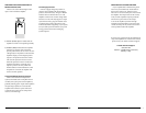
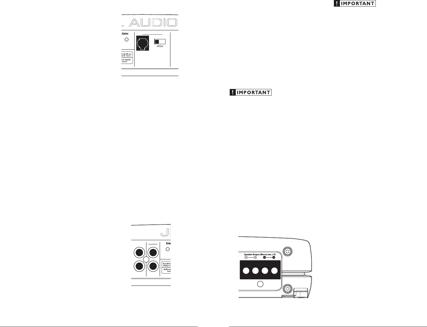
SPEAKER OUTPUTS
The A1400’s speaker outputs are designed to
accept 16 AWG - 8 AWG wire.
The A1400 is designed to deliver power into
speaker loads equal to or greater than 2 ohms.
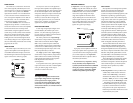
To connect the speaker wires to the amplifier,
first back out the set screws own the top of the
terminal block, using the supplied 2.5 mm hex
wrench. Strip 1/2 inch (12 mm) of insulation from
the end of each wire and insert the bare wire into
the terminal block, seating it firmly so that no
bare wire is exposed. While holding the wire in
place, tighten the set screw firmly, taking care not
to strip the head of the screw.
Speaker loads below 2 ohms nominal are not
recommended and may cause the amplifier
to initiate a protection mode which reduces
power output.
You will notice that there are two “+” positive
connections and two “–” negative connections.
This is to facilitate multiple speaker wiring.
The two positive and two negative connections
are connected in parallel inside the amplifier.
Connecting two speakers, each to one set of
positive and negative terminals, will result in a
parallel speaker connection. If only connecting
one pair of speaker wires, it is not necessary to
use both sets of connections.
JL AUDIO A1400 9
Tuning Hint: A trunk mounted sub whose
output has to “fight” through a rear deck or a
back seat often benefits from the 12 dB/octave
slope which lets more upper bass content pass
through. A sub that fires directly into the
listening environment is more likely to benefit
from a 24 dB/octave slope.
Note: The above hint is not “set-in-stone”… You
should always listen to the system carefully to
determine the best choice as vehicle acoustics and
other factors play a big role in choosing the most
appropriate filter slope.
3) Precise Frequency Selection: The filter
frequency markings on the front panel of
the amplifier are for reference purposes and
are generally accurate to within 1/3 octave
or better. If you would like to select the filter
frequency with a higher level of precision,
consult Appendix B (page 13) of this manual.
This chart gives you a more accurate frequency
for each of the forty detented positions of the
frequency selection control. This method can
be very useful if the amplifier is mounted in
a location where you can’t see the front panel
markings easily.
4) Defeating the Amplifier Filter: The Low-
Pass filter can also be defeated completely,
by switching the “Mode/Slope” switch to
the “Off” position. This is useful if you are
using an external active crossover in the
system. Keep in mind that turning the internal
crossover off also defeats the “Bass Boost”
processing (see next section for details). With
the internal crossover turned off, the A1400’s
upper frequency response limit is 250 Hz, due
to its bass-specific Class D design.
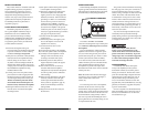
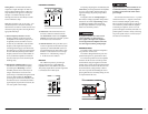
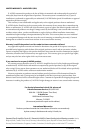
BASS BOOST CONTROLS
Bass Boost Controls
Bass Boost
Remote
Bass Port
Protect
1) “Bass Boost”: This switch allows the user
to activate a 6 dB boost centered at 48 Hz.
The “Filter Mode” switch in the “Amplifier
Controls” section must be in the “LP” position
for the bass boost to be functional.
2) “Remote Bass Port”: This port allows you to
connect an optional remote boost knob (sold
separately, JL Audio Model RBC-1) that can
be mounted in the front of the vehicle. With
the RBC-1 connected, the boost is no longer
limited to 0 or +6 dB, allowing a range of
0 - 12 dB of boost to be selected.
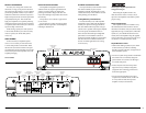
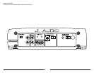
PREOUTS
The A1400 incorporates a pass-through
preamp output section, so that additional
amplifiers can be easily added to the system.
The preamp output delivers the same signal that
is connected to the A1400’s inputs.
CH 1 (Left)
Power
CH 2 (Right)
Pre-Outs
8 JL AUDIO A1400