


E-7 E-8
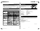
FOR TABLE TOPUSE
FOR WALLMOUNTING
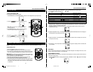
1.Usethewall-mountingtemplatesuppliedwiththeunittomakemarksonthewall for the anchors.Make sure
themarksarelevel.
2. Drill 1/4" holes on the marks. P lease refer to the appendix sheet attached with this instruction manual
for details.
3. Insert the plastic anchor suppliedwith unit until itis flush with the wall.
4. I ns e rtthe s cre wa nd tighte n the scre w4mm awa y from the wa ll. ( Approxima tely the width of 2 pennie s )
Ha ng the main unit a nd s pea ke rs tothe s cre wa s indic ated below:
GETTINGSTARTED
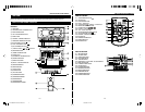
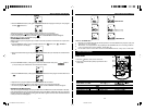
SPEAKER CONNECTION
1.Insertthespeakercables bypushingdowntheterminalleveroftheLeftSpeakerTerminalandtheRight
SpeakerTerminal(25).
2. Connect the speaker to S peaker Terminals (25), with red wire to red terminals and black wire to black
termina ls .
LINE IN(AUX IN)CONNECTION(OPTIONAL)
1. Connect the leftand rightchannel R CA plug (notincluded) into the AUX IN Jack (21) and the other end
to your external player. Make sure the polarity of the rightand the leftchannel is correct, Red to Right, White to Left.
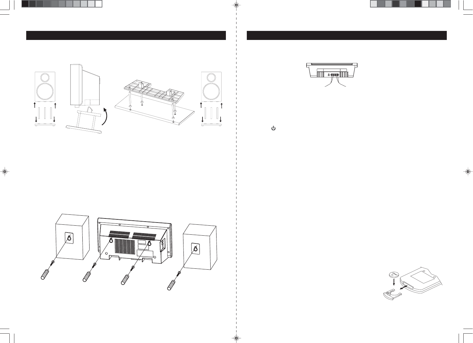
2. Press the
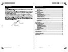
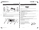
Following the diagrams below, insert the stands into the base and attach the main unit and
speakers as shown.
NOTE: A screwdriver is needed for attacking the stands to the main unit and stands.
ON/STANDBYButton(10/H1)toswitchontheunit.
3.PressFunctionButton(3/H3).“AUX”Indicator(#D5)appearsinthedisplay(18).
4.Playtheauxiliaryinputsource.
SUBWOOFERCONNECTION (OPTIONAL)
1.ConnectoneendofaRCAplug(notincluded) intotheSubwooferJack(24)andtheotherendtothe
subwoofer (not included).
2.Turnontheunitandthenyoursubwoofer.
ANTENNACONNECTION
FM:UnwrapandfullyextendtheFMAntennawire(22)forbestreception.Ifstereobroadcastingisreceived,
Stereo Indicator (#D15) will light.
AM:Theunitisbuilt-inwithadirectionalferriteantenna,reposition theunitforbestreception.
POWERSUPPLY
ThisFrontLoadingDualCDSystemoperatesfromAC120V~60Hzlinepowersupply.
Theremotecontrolunitoperatesonone 3V“CR2025”lithiumbattery.Topoweruptheremotecontrol,removethe
plasticinsulationtabstickingoutofthebatterycompartment.
ACPOWERCONNECTION
Connectthepowercordto anAC120V~60Hzpowersource.
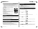
REPLACINGBATTERYINTHEREMOTECONTROL
1.Turn overtheremotecontrol,andremovethebatterydoor.
2.Install1“CR2025”lithiumbatteryaccordingtothepolaritydiagram
on the battery compartment.
3.Replacethebatterydoor.
INSTALLATION
JMC-670 INSTRUCTION MANUAL JMC-670 INSTRUCTION MANUAL
HX-1056M3 IB JENS 001 REV0.P65 7/20/2005, 2:51 PM5