


JBR550
3
INSTALLATION
Before You Begin
1. Disconnect Battery
Before you begin, always disconnect the battery negative terminal.
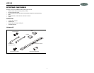
2. Remove Transport Screws
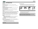
Important Notes
• Before final installation, test the wiring connections to make sure the unit is connected
properly and the system works.
• Use only the parts included with the unit to ensure proper installation. The use of
unauthorized parts can cause malfunctions.
• Consult with your nearest dealer if installation requires the drilling of holes or other
modifications to your vehicle.
• Install the unit where it does not interfere with driving and cannot injure passengers if
there is a sudden or emergency stop.
• If the installation angle exceeds 30º from horizontal, the unit may not give optimum
performance.
• Avoid installing the unit where it will be subject to high temperatures from direct sunlight,
hot air, or from a heater, or where it would be subject to excessive dust, dirt or vibration.
DIN Radio Installation
This unit is designed for installation in vehicle cabs with an existing 1-DIN radio opening. In
many cases, a special installation kit will be required to mount the radio to the dashboard.
These kits are available at electronics supply stores and car stereo specialty shops. Always
check the kit application before purchasing to make sure the kit works with your vehicle.
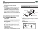
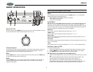
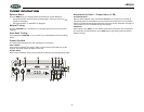
Universal Installation (Using Mounting Sleeve)
1. Slide the mounting sleeve off of the chassis. If it is locked into position, use the removal
keys (supplied) to disengage it.
2. Check the dashboard opening size by sliding the mounting sleeve into it. If the opening is
not large enough, carefully cut or file as necessary until the sleeve slides easily into the
opening. Do not force the sleeve into the opening or cause it to bend or bow. Check that
there will be sufficient space behind the dashboard for the radio chassis. Connect wires
prior to actually installing the sleeve. Pigtail wiring should take place after hole size is
confirmed. Mount sleeve after wiring.
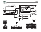
3. Follow the wiring diagram carefully and make certain all connections of the wiring harness
are properly secured and insulated to insure proper operation of this unit. After completing
the wiring connections, turn the unit on to confirm operation (ignition switch must be “on”).
If unit does not operate, recheck all wiring until the problem is corrected. Once proper
operation is achieved, turn off ignition switch and proceed with final mounting of the
chassis.
4. Locate the series of bend tabs along the top, bottom, and sides of the mounting sleeve.
With the sleeve fully inserted into the dash opening, bend tabs outward so that the sleeve
is firmly secured to the dashboard.
5. Carefully slide the radio into the mounting sleeve making sure it is right side up until it is
fully seated and the spring clips lock it into place.
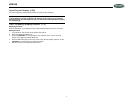
6. Attach one end of the perforated mounting strap (supplied) to the screw stud on the rear
of the chassis using the flange nut provided. Fasten the other end of the perforated strap
to a secure part of the dashboard, either above or below the radio using the screw and
flange nut provided. Bend the strap to position it as necessary.
CAUTION: The rear of the radio must be supported with either the perforated strap or
the rubber mounting bushing to prevent damage to the dashboard from the weight of
the radio or improper operation due to vibration.
Kit Installation
1. If your radio requires the use of an installation kit to mount this radio, follow the instruc-
tions included in the kit to attach the radio to the mounting plate supplied with the kit.
2. Wire and test the radio as described.
3. Install the radio/mounting plate assembly to the sub-dash according to the instructions of
the installation kit.
4. Attach the support strap to the radio and dashboard as described above.
5. Replace the dashboard trim panel.
I
N
T
SECURE THIS END TO
SUB-DASH STRUCTURE
PERFORATED SUPPORT STRAP
MOUNTING SURFACE OPENING
NOTE: IF OPENING DOES NOT EXIST,
USE MOUNTING SLEEVE AS A TEMPLATE
AND CUT OPENING. FILE EDGES TO FIT
IF NECESSARY. DO NOT OVER FILE.
SECURE THIS END TO
REAR OF RADIO
DIN MOUNTING SLEEVE
LOCKING TABS
REAR SUPPORT SCREW
REMOVAL KEYS
MOUNTING
SURFACE
MOUNTING
SLEEVE
BEND TABS
BOTTOM TAB
BEND DOWNWARD 90°
MOUNTING TAB DETAILS
CUTAWAY VIEW OF
MOUNTING SURFACE
SIDE VIEW
TOP TAB BEND
UPWARD 90°