


Signal Connections
T
he Model 2 amplifier offers unprecedented compatibility with associated
audio components. When connecting or disconnecting speaker or
interconnect cables, it is only necessary that the FRONT PANEL STANDBY/
POWER button be pressed to switch the amplifier to standby mode. The
button will not be illuminated in this mode.
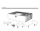
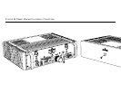
1 When installing the interconnect cables, a slight click may be heard
when the XLR interconnect plugs are installed correctly and latched.
The latch (located on the input connector and labeled PUSH) must be
pressed to remove the XLR interconnect cable.
2 When using RCA unbalanced interconnects from your preamplifier or
other source component, install the supplied XLR/RCA adapters into
both XLR input connectors. The Amplifier will still operate in the fully
balanced (Differential Mode™) configuration.
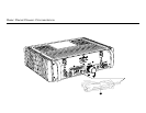
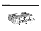
3 Unscrew RIGHT CHANNEL OUTPUT and LEFT CHANNEL OUTPUT
connectors and install the positive and negative loudspeaker cable
spade terminals to the respective Amplifier OUTPUT. Red is normally
positive; black is normally negative. ALWAYS USE THE SUPPLIED
SPEAKER TERMINAL HAND WRENCH WHEN CONNECTING OR
DISCONNECTING LOUDSPEAKER CABLES. DO NOT OVERTIGHTEN
THESE TERMINALS.
WARNING: Both positive and negative OUTPUTS of both
channels are electrically active with respect to chassis and/or system
ground potential. It is important that both of these outputs are electrically
isolated from system ground potential. This precludes the use of this
Amplifier in certain loudspeaker switching configurations (sometimes used
in retail demonstrations) and testing or servicing situations where either
positive or negative outputs can be connected to ground potentials.
Failure to observe these precautions may result in damage to the Amplifier
and may void your warranty. Consult the factory first if the Amplifier is to
be used under these conditions.
Remote
4
A REMOTE connector (DIN 5-pin) is provided on the rear panel for
remotely switching the Amplifier between operational and standby
modes. The pin connections on this connector parallel the electrical
contacts of the FRONT PANEL STANDBY/POWER button and lamp. An
optional wired remote switch or infrared wireless remote sensor can be
plugged into the REMOTE connector to facilitate this function. Contact
your dealer or Jeff Rowland Design Group for further information and
availability of this feature.
Signal Connections
!