


© Jeff Rowland design gRoup 2007. all Rights ReseRved.
NOTE: Due to the exceptionally low power consumption rating of the Model 312, it is
recommended that the unit not be disconnected from AC mains unless the amplier is to be
moved or reinstalled in another location. It is recommended that the amplier be placed in
Standby mode rather than disconnected from the AC mains power when the amplier is not
in use.
WARNING: If the unit is plugged into a voltage different from the range listed on the back
panel, serious damage to internal circuitry will result and will void the warranty.
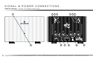
STEP 1:
Verify that the VOLTS AC input identified on the rear panel
near the AC input socket is the same as the AC mains voltage
in your area. If the voltage does not match, DO NOT CONNECT THE
AMPLIFIER TO AC POWER and contact your dealer immediately.
STEP 2:
Verify that the AC MAINS circuit breaker is closed (no white
area visible on breaker).
STEP 3:
Install the AC Power Cable between the amplifier and your AC
mains outlet.
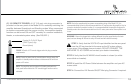
STEP 4: Connect the 12V Remote ON/OFF Mini-plug Connector if required.
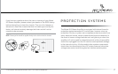
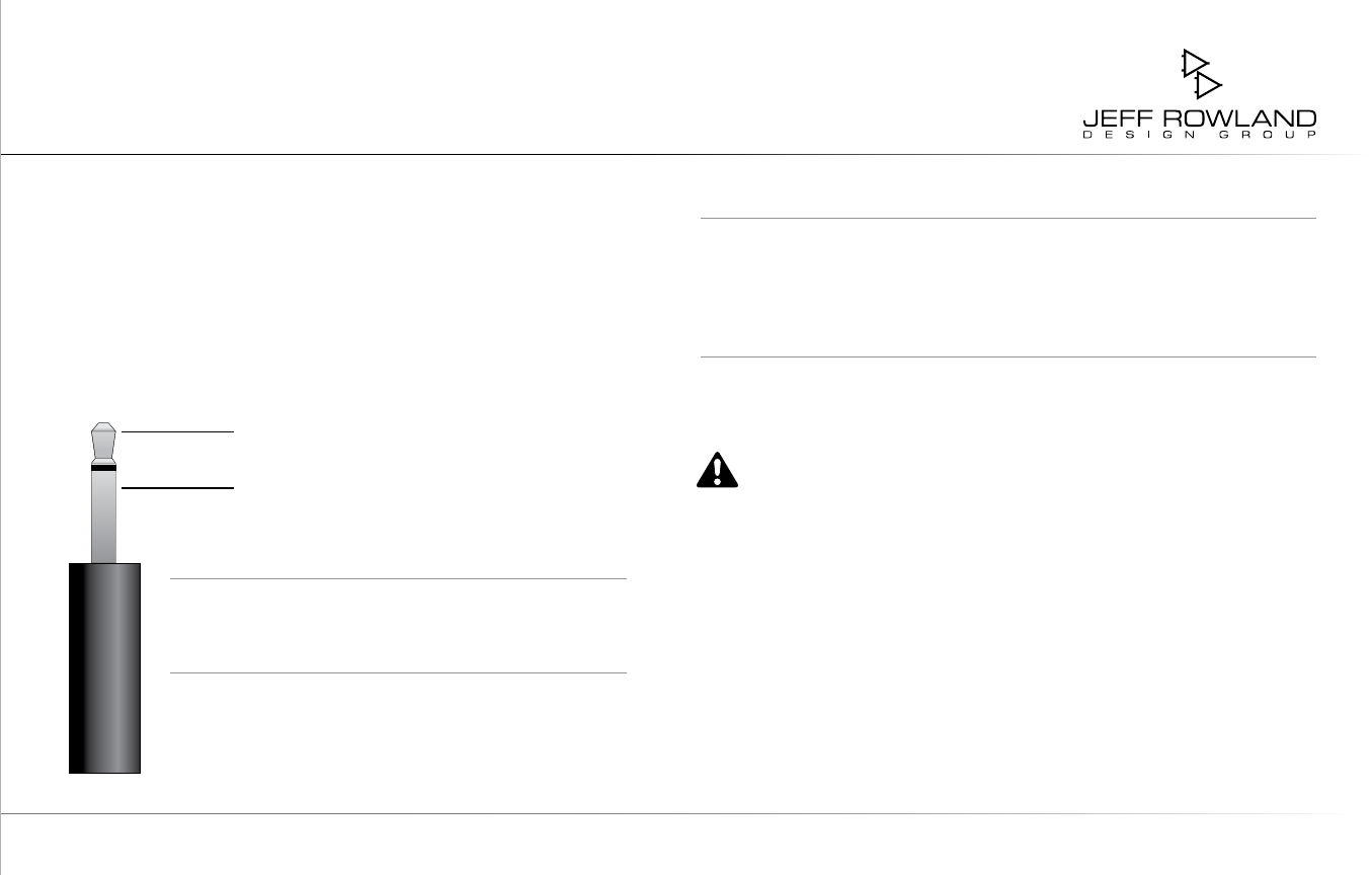
(F) 12V REMOTE TRIGGER: A 1/8” (3.5 mm) mini-plug connector is
provided on the rear panel of the Model 312 for remotely switching the
amplifier between Operational and Standby modes. When connected
to another component with the proper circuitry, the amplifier standby
function can be turned ON and OFF remotely in a custom installation,
theater, or automated system setup. (See FIGURE 1)
FIGURE 1: Detail of 12V remote trigger and mini-plug connector
requirements
NOTE: Please be aware that the remote feature simply places the
amplier in standby mode and does not disconnect the unit from
power or AC mains.
NOTE: The amplier must be placed in Standby mode with the
front panel button before the 12V remote trigger function can be
activated.
Constant 3v To 15v DC Signal
(12VDC Typical) (tip)
Ground (sleeve)