The installation system has been designed so that the
entire installation can be accomplished from beneath the
ceiling, for instances when access above the tile is not
possible or practical. However, in some cases it may be
easier with removable ceiling tiles to access from both the
top and bottom of the ceiling tile during various phases of
the installation.
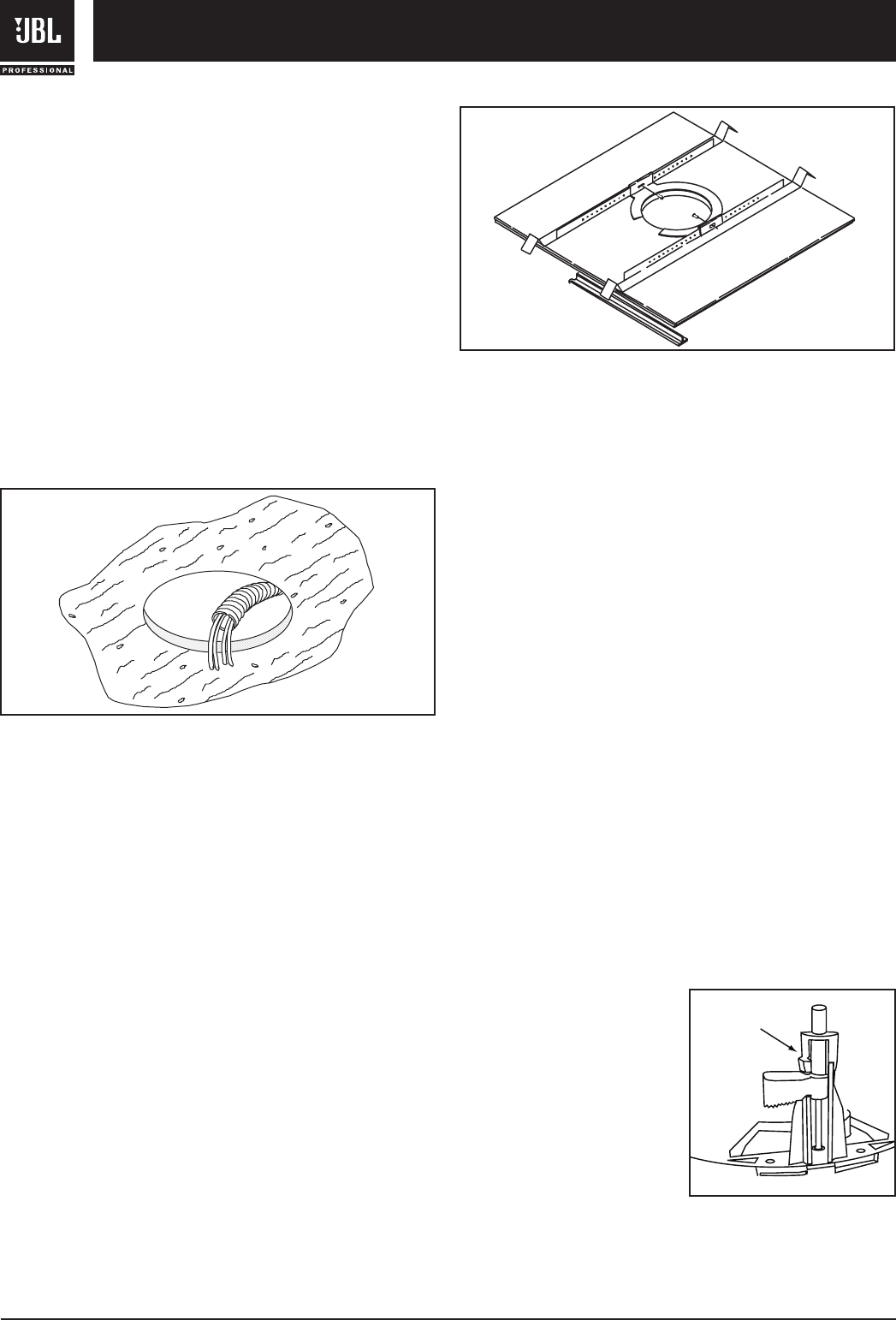
Step 1 – Cut the Hole. Cutout the hole size either by
tracing the cardboard cutout template or with a circular
cutter set to the cutout sizes listed below and pull the
wiring through the cutout hole.
Control 42C: 4.1 inches (104 mm)
Control 47C/T: 11.1 inches (282 mm)
Control 47LP: 11.1 inches (282 mm)
Control 47HC: 12.1 inches (307 mm)
Control 40CS/T: 12.1 inches (307 mm)
Step 2 – Insert Backing Hardware Through the Hole.
Packaged with the speakers are two types of backing
hardware – a C-shaped backing-plate bracket and two tile
rails (except for the lightweight Control 42C which does
NOT include tile rails).
Suspended Ceilings – Insert the C-plate through the hole
cut in the ceiling tile. Place the C-plate around the hole
with the tabs pointing upwards enabling the C-plate to lie
flat on the tile. Insert the tile rails through the cut hole in
the ceiling tile. Snap the two rails into the two tabs in the
C-plate and align the rails so that the ends extend OVER
the T-channel grid on the side of the tile. Secure the rails
onto the C-bracket tabs by inserting a screw through each
tab into the rail. This can all be accomplished from below
the ceiling tile, if necessary.
For safety when installing in suspended ceiling tiles, utilize
all included brackets. Note that the lightweight Control 42C
includes a C-ring only, which may be all that is required for
some applications. If the application calls for tile rails, they
are available separately as part number MTC-RAIL.
Tile Rails: The tile rails are designed to fit either standard
24-inch wide tiles or 600-mm wide tiles. The tile rail pieces
do NOT physically attach to the T-grid struts. Instead, the
inverted-V shape at the ends of the rails sit OVER the T-
grid strut. During normal operation, the rails are supported
by the edge of the tile. In the unlikely event that the tile
comes out or falls apart, the ends of the support rails are
designed to catch onto the T-grid, providing secure support
to hold the loudspeaker assembly in place.
Vibration Reduction: These loudspeakers can generate
substantial vibration, which can cause buzzing of the
ceiling materials or structure. Depending on the character
of the ceiling tile and structure, the installer might need to
place neoprene or other dampening material under the tile
rails or the edges of the tiles to address rattles from the
ceiling materials.
Cutout Placement: The tile rails are pre-punched with
attachment holes along their length. Placement is not
limited to the center of the tile as is the case with many
other tile rail support systems.
Non-Suspended Ceiling Types – The C-bracket can be
optionally used by itself to shore up the ceiling material
and to spread out the clamping force from the tab clamps.
Insert the C-plate through the cut hole in the ceiling and
place it on the back side of the hole before inserting the
speaker.
Two Landing Dog-Ears
– All Control 40 Series
Loudspeakers (except the
Control 42C) are equipped
with a two-landing dog ear
suspension system enabling
them to be used with ceiling
tiles that are up to 70 mm
(2.75 inches) thick. If using
Control 40 loudspeakers with
ceiling tiles that are greater
than 54 mm (2.125 inches) thick, start with the dog ear in
the second (top) landing to ensure clearance and ease of
installation.
CONTROL 40 SERIES INSTALLATION
Hole Cutout
4
JBL Professional Control Contractor 40 Series
Second Landing
C-Bracket and Tile
Rail Positioned on
Ceiling Tile


