5
JBL Professional Control Contractor 40 Series
WIRING INSTRUCTIONS
Control Contractor 40 Series in-ceiling loudspeakers
include Euroblock locking input connectors that allow the
system to be “pre-wired”.
Connecting the Wiring to the Euroblock
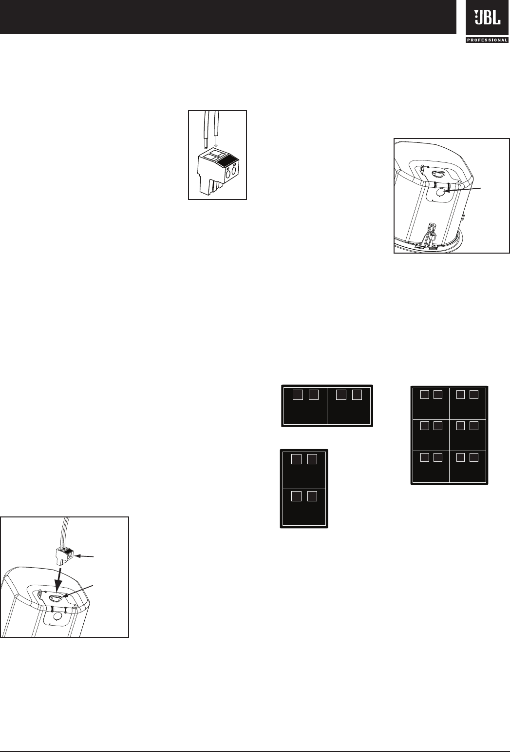
-- Connect the wiring to the removable
locking connector that is INCLUDED with
the speaker by stripping the insulation back
about 5 mm (about 3/16 inch), inserting
the bare end of wire into the connector and
screwing down the hold-down screw until
tight using a small flatblade screwdriver.
Tighten any unused screws to avoid
vibration. Using terminal block connectors
allows the system to be pre-wired before final installation
of the product.
When wiring Control Contractor 40 Series
loudspeakers, always use proper electrical wiring
practices in accordance with your area’s building
codes and regulations.
Connecting the Input Terminal Block on Control
Contractor 40 Series Loudspeakers -- The input terminal
cover on all Control Contractor 40 Series are fitted with a
conduit connector for securing wiring conduit to and from
the unit. To wire the unit:
1. Loosen the screw on top of the input terminal cover and
then remove (and save) the input terminal cover screw on
the side of the can.
2. Swing open the input terminal cover and remove the
euroblock connector.
3. Insert the bare ends of wire into the Euroblock connector
and secure the wires with the hold-down screws. (see
Connecting the Wiring to the Euroblock)
4. Loosen the conduit
connector on the input
terminal cover and insert
the wired euroblock
connector through
the conduit connector
opening. Connect the
euroblock to the matching
receptacle.
5. Close the input terminal cover and tighten the terminal
cover screws.
6. Allowing sufficient strain relief slack for the input wiring
and re-tighten the conduit connector on the terminal
cover.
NOTE: The input terminal
cover on Control Contractor
40 Series loudspeakers
includes a .75 in (19 mm)
knockout for an additional
conduit clamp. This knockout
point can be used in addition
to the conduit connector
located on the top of the can
and is useful for wiring loop-
thru runs or when access is
limited on the top of the can.
Guide to Connection Pins on Control 40 Loudspeakers
-- There are two (2) removable locking input connectors
with two (2) terminals on each for the Control 42C, Control
47C/T, Control 47LP and Control 47HC and six (6) terminals
on the Control 40CS/T. The pin functions are listed on the
label located on the can.
To wire Control 40 Series loudspeakers simply connect
the positive wire to the “+” pin and connect the negative
wire to the “-” pin. The “IN” pins are paralled to the “LOOP
THRU” pins (+ and - respectively) inside the loudspeaker.
The “Loop Thru” pins allow a parallel connection to an
additional loudspeaker.
To select the operating mode or desired output tap of the
loudspeaker, simply rotate the tap selector switch located
on the front of the baffle to the desired setting.
Note: Both 70V/(100V) connections and low impedance
connections are made via the same input pins. When
using the transformer tap selections, be sure that the
power amplifier is set on 70V/(100V) mode and the leads
feeding the system are connected to 70V/(100V) outputs
on the amplifier.
+
-
2-pin Connector
+
-
Euroblock
Connecto
r
Conduit
Connector
Knockou
t
+
-
Loop
Thru
Loop
Thru
+
-
IN
IN
+
-
Sat 1
+
-
Sat 2
+
-
Sat 3
+
-
Sat 4
Loop
Thru
Loop
Thru
+
-
IN
IN
+
-
Loop
Thru
Loop
Thru
+
-
IN
IN
+
-
Control 47C/T, LP & HC:
+
-
Loop
Thru
Loop
Thru
+
-
IN
IN
+
-
Sat 1
+
-
Sat 2
+
-
Sat 3
+
-
Sat 4
Loop
Thru
Loop
Thru
+
-
IN
IN
+
-
Loop
Thru
Loop
Thru
+
-
IN
IN
+
-
Control 40CS/T:
+
-
Loop
Thru
Loop
Thru
+
-
IN
IN
+
-
Sat 1
+
-
Sat 2
+
-
Sat 3
+
-
Sat 4
Loop
Thru
Loop
Thru
+
-
IN
IN
+
-
Loop
Thru
Loop
Thru
+
-
IN
IN
+
-
Control 42C:


