


5
0
1
2
3
4
5
6
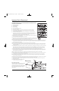
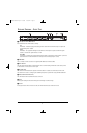
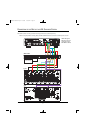
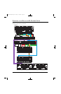
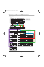
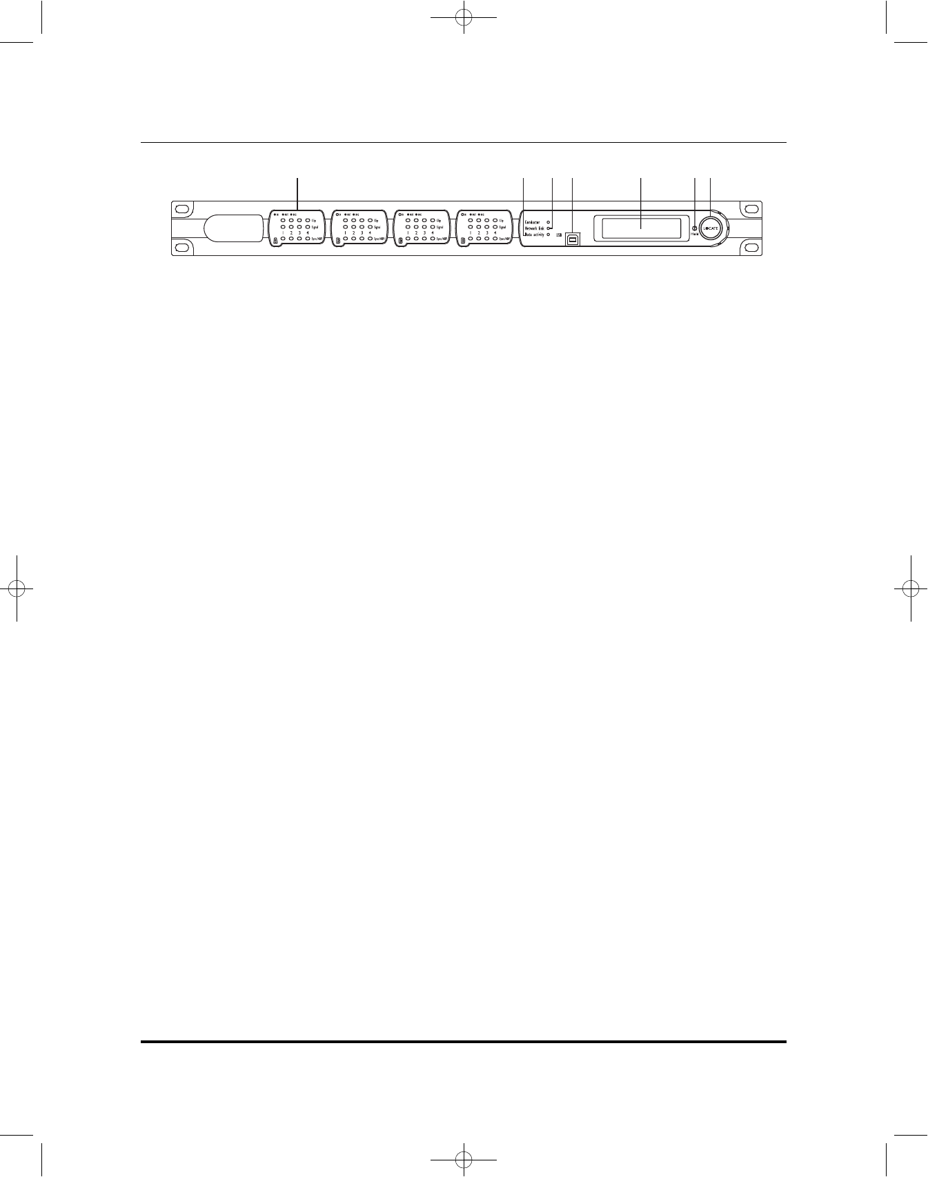
DETAILED DIAGRAM –FRONT PANEL
0 INPUT/OUTPUT CARD MONITORING
Each channel has three LED indicators showing:
CLIP
Illuminated – Indicates clipping in the analog domain for each channel of the fitted input or output card.
The LED will light at +18.5dB.
SIGNAL
Illuminated – The signal LED will light for each channel of a fitted input or output card when the signal
reaches or exceeds the signal threshold of –20dB.
SYNC/48V
This feature is currently not supported by JBL Synthesis (lights to indicate that +48V “phantom” power has
been activated for the relevant channel of a fitted input card or that Digital Sync is valid).
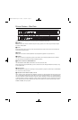
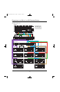
1 USB PORT
This is currently for future use and is not supported (SDEC 4500 does not include USB).
2 DATA ACTIVITY
The data activity LED will flash to indicate that the device is communicating with another control device, either
on the network or via the serial or control ports.
3 NETWORK LINK
The network link LED indicates the presence of Ethernet cables. If no cables are connected, the LED is unlit.
The network link is used for configuring and calibrating the Synthesis system when using the DACS calibration.
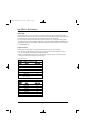
4 LCD (LIQUID CRYSTAL DISPLAY)
The LCD indicates the name/ID and IP address of the unit.
5 HOLD
Pressing and holding the Hold switch will cycle the LCD through its contrast range.
6 LOCATE
Pressing the Locate switch on the front of the unit will illuminate the Locate switch on the rear.
SDEC3000.4500.om.qxd 4/16/09 10:06 AM Page 5