6
7
9
8
A
B
C
D
SDEC-3000
SDEC-4500P and
SDEC-4500X
BlueLink
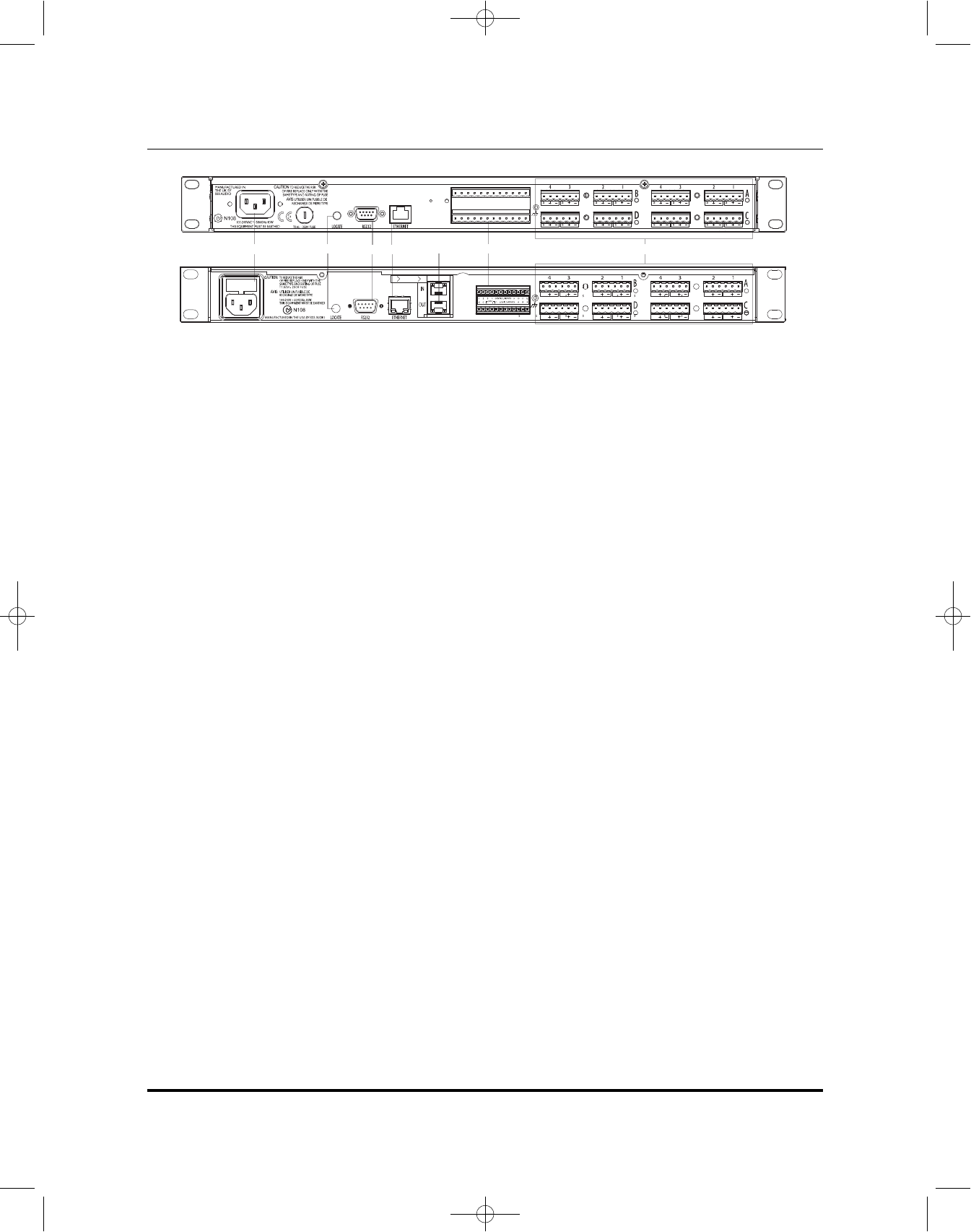
7 AC MAINS
AC Mains input to the universal switched-mode power supply; operates over a wide range of AC input voltages
from 85V to 270V, 50/60Hz.
8 LOCATE
Pressing the Locate switch on the rear of the unit will illuminate the Locate switch on the front and identify the
device within the DACS software.
9 RS-232
Serial port for connection of external calibration and configuration equipment not used at this time.
A ETHERNET
The main connection for the proprietary system control network, and for third-party Ethernet control. The SDEC
must be connected to an Ethernet hub during the calibration process.
B BLUELINK
™
CONNECTORS (SDEC-4500 ONLY)
The SDEC-4500P and SDEC-4500X use BlueLink to send and receive audio data.
Please Note: When using the SDEC-4500, you must connect the two units through the BlueLink connection, using
a Cat. 5e patch cable.
C CONTROL INPUTS
The SDEC-4500 can be configured for full-range or bi-amp operation by using these control inputs. The SDEC-3000
does not need or use this connection.
D INPUT/OUTPUT CARD POSITIONS A, B, C AND D
These connectors provide the balanced and unbalanced connections for the input/output card fitted in the four card
slots in a JBL Synthesis SDEC device. A green LED next to the slot assignment letter A, B, C or D indicates that an
input card is fitted and an amber LED when an output card is fitted. The analog connections are balanced/unbalanced,
on Phoenix/Combicon connectors. Depending on which model and configuration you have purchased will determine
which input/output card has been installed at the factory. Please make sure to order the correct wiring kit, either
S3000IC or S4500IC, with your system.
DETAILED DIAGRAM –REAR PANEL
SDEC-3000 has no BlueLink
™
connections, but is otherwise identical to the SDEC-4500P and SDEC-4500X.
SDEC3000.4500.om.qxd 4/16/09 10:06 AM Page 6


