


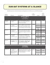
Sub-Sat Design Considerations
Sound Level Capability
For each system in this guide, the Max SPL figure is listed,
describing the continuous sound level that the system can
maintain on a full-range basis with either speech or music
program content, with 10 dB headroom for clear transient
peaks.
For any installation, the satellite speakers might be located
next to each other and cover exactly the same area, resulting
in 6 dB of coupling between them, or they might be located
far apart and have no overlap between then resulting in no
coupling. e Max SPL figures listed in the charts assume
somewhere in between, that there is some degree of overlap
in coverage but not full overlap. erefore, a coupling figure
of 3 dB is utilized.
Actual Max SPL
For applications where there is very little overlap of satellite
speakers, the actual Maximum SPL will be 3 dB lower for
2 satellite speakers (and 6 dB lower for 4 satellite speaker)
than what is listed. For applications where there is almost
full overlap (satellite speakers covering the same area), the
actual Maximum SPL will be 3 dB higher for 2 satellite
speakers (and 6 dB higher for 4 satellite speakers).
Subwoofer Location’s Affect on Sensitivity
and Maximum SPL
e system performance figures listed are based on the
subwoofer being located away from boundary junctions
and corners. For applications where the subwoofer will be
placed at a 2-surface boundary junction (wall/floor, wall/
ceiling, wall/wall), both the Sensitivity and the Maximum
SPL of the subwoofer increases by 6 dB. For applications
where the subwoofer is placed as a corner junction (wall/
wall/ceiling or wall/wall/floor), the Sensitivity and the
Maximum SPL of the subwoofer increases by 12 dB.
is can unbalance the subwoofer satellite sensitivity
balance. It is a good idea to have an equalizer in the sound
system to be able to adjust the bass level for proper balance.
A parametric EQ allows for the best adjustment. For
graphic EQ, a minimum of 15 bands is usually required to
be able to set the EQ break point at the proper frequency.
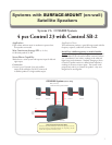
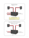
Using the MTC-210-SAT Input Module
ALL these systems (except the CCS6000 System that utilizes
a SB-2 subwoofer) utilize the MTC-210-SAT input module
installed in the back of the Control SB-210 subwoofer.
is module provides a full passive crossover consisting
of a high-pass to the satellite speakers and low-pass to the
subwoofer drivers.
4 Ohm / 8 Ohm Setting
(ie, Satellite Speaker Impedance Selector)
e module contains a header adjustment for setting the crossover
to work properly with either 4 ohm or 8 ohm satellite loads per
output.
Mono / Stereo Setting
e module also contains a header to set the system to operate
either as a mono system with a single input (+ and -) wired to
the Left/Mono input terminals, or as a full stereo system with
Left input wired to Left input terminals and right input wired to
Right input terminals.
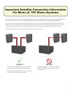
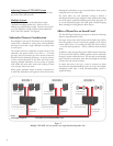
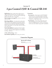
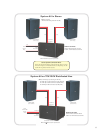
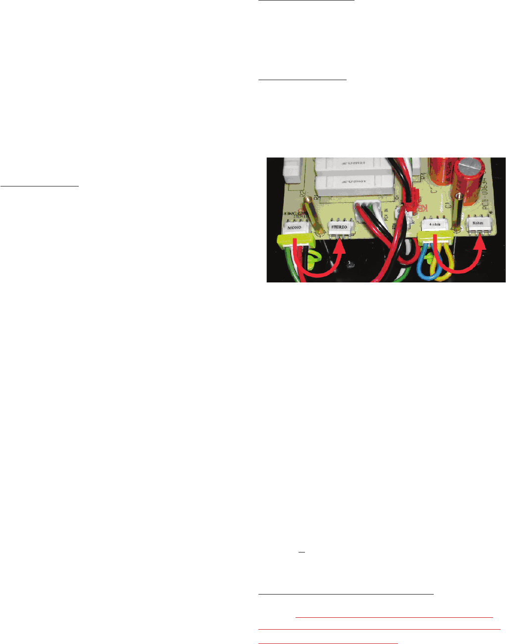
Figure 1
Setting Mono/Stereo and Satellite Impedance Headers
on MTC-210-SAT (and MTC-210T-SAT) Input Module
Mono/Stereo and 4/8 Ohm selection is accomplished by
moving the headers on the MTC-210-SAT Input Module before
installing the module into the subwoofer. Yellow indicators move
with the headers, annunciating the selected modes visibly on the
back panel of the subwoofer after the module is installed. Header
positions shown in the picture above are set to Mono with 4
ohms per channel of satellite speakers. Moving the headers in the
position of the red arrows changes the settings to Stereo with 8
ohms per channel of satellite speakers.
Operation from a 70V/100V Distributed
Speaker Line
A different SB-210 input module needs to be purchased for
operating a subwoofer satellite system via 70V/100V. It is model
MTC-210T-SAT, which includes input 70V/100V transformers
as well as the built-in crossover network.
Speaker Type for 70V/100V Systems
Satellite speakers remain LOW-IMPEDANCE (non-T)
models. DO NOT use T-version satellite speakers for any
of the satellite speakers, even those systems operated from a
70V/100V distributed speaker line.
4 5