


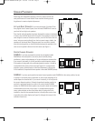
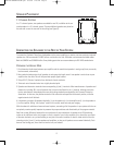
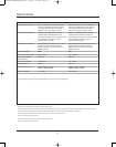
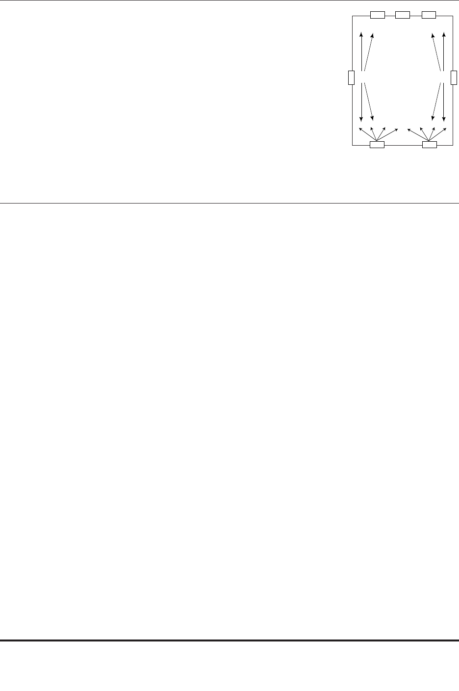
7.1-CHANNEL SYSTEMS
In a 7.1-channel system, two speakers are added for rear fill, in addition to the sur-
round speakers in a 5.1-channel system. The two additional speakers are placed on
the rear wall or near the rear wall in the ceiling (see Figure 6).
6
RCL
SIDE
LEFT
SIDE
RIGHT
R
EAR LEFT
R
EAR RIGHT
Figure 6. 7.1-Channel system
SPEAKER PLACEMENT
To connect the Synthesis Three Array loudspeakers to the power amplifiers or receiver, use two-conductor insulated
speaker wire. We recommend #14 AWG wire as a minimum size. Your JBL dealer can recommend suitable cables.
Both the SAM3VA and SAM3HA utilize 5-way binding posts that can accommodate up to #10 AWG stranded wire.
PREPARING THE HOOKUP WIRE
1. First determine the distance between your amplifier and the most distant speaker in each group (fronts, surrounds,
back surrounds, subwoofers).
2.
Now make the hookup wires for all speakers in each group this length, even if one speaker is much closer
to your
amplifier than the other. This will help maintain proper signal balance.
3. Strip off 3/8" (10mm) of insulation from both ends of each conductor.
4.
Twist each set of standard wires into a tightly bunched spiral.
5.
Speakers and electronics terminals have corresponding (+) and (–) terminals. Most manufacturers of speakers and
electronics, including JBL, use red to denote the (+) terminal and black for the (–) terminal, although some elec-
tronics manufacturers have adopted the new color-coding standard promulgated by the Consumer Electronics
Association. In that case, the positive terminal will be colored to correspond to the channel position, while the
negative terminal will be black.
It is important to connect all speakers identically: (+) on the speaker to (+) on the amplifier and (–) on the speaker to
(–) on the amplifier. Wiring “out of phase” results in thin sound, weak bass and poor imaging.
With the advent of multichannel surround sound systems, connecting all of the speakers in your system with the cor
-
rect polarity remains equally important to preserve the proper ambience and directionality of the program material.
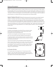
Now find a visual difference between the two conductors of each molded pair of speaker wires. Differentiating
marks can be a different color wire (copper or silver); a strand of yarn in one conductor; thin, raised ribs on one part
of the outer insulation; or a printed marking on one part of the outer insulation. It doesn’t matter which of the two
strands go to the (+) and (–) on the speakers and amplifiers, as long as all speakers are connected identically. Push
down on the binding post, insert the wire into the hole, and release.
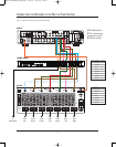
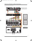
CONNECTING THE SPEAKERS TO THE REST OF YOUR SYSTEM
SYNP1032-SAM3HA-VA-OM.qxd 10/2/06 9:25 AM Page 6