


19
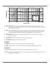
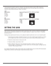
3 - LEVEL: Sound level adjustment. The 12 o’clock position is a good starting point for most usages. Once the
full-range system has been connected the level can be varied to match and deliver the desired
balance (for details see Setting the Gain on page 21).
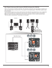
6 - POWER SWITCH: Turns the power on. Power “on” status is indicated with the illumination of the logo on the grille.
7 - LINE SELECT: Allows the user selection for different local voltage ratings.
8 - AC LINE INPUT: Standard IEC AC mains input connector.
Indicators
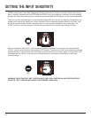
4 - SIGNAL: Signal indicator. The green LED illuminates when a signal is present at the input connector.
5 - OVERLOAD: The red LED illuminates when the system overload protection is active. If the input signal is too
strong or the “LEVEL” control set too high, the red LED will illuminate constantly. Illumination of the
“OVERLOAD” LED can be avoided by reducing the input level or turning down the “LEVEL” control
to the point at which the red LED occasionally flickers.
Connectors
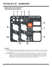
9 & 11 - XLR: 1/4 inch phone jack balanced input connector.
(see Reference section page 26 for information).
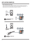
10 & 12 - XLR: Male balanced output connector. This connector provides a full-range or high-passed signal.
dependent on the setting of the “XOVER” switch. In addition to connecting a full-range system to the
output, it’s also possible to daisy chain subwoofers together.
Note 3:
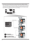
A single subwoofer can be used with a stereo source. The integral differential circuits sums the low frequency
information from the left and right channel to a mono signal, ready for reproduction by the subwoofer.