


4
Mounting the Amplifier
The JBL P-4020 (or P-4040) can be
mounted in virtually any location inside
the vehicle. However, make sure to keep
the amplifier away from heater vents or
ducts.
1. At the chosen site, use the amplifier as
a mounting template and mark the
locations of the four mounting holes.
2. Drill a small pilot hole at each marked
location.
3. Mount the amplifier and securely
tighten the mounting screws.
Wiring the Power Connections
Refer to diagrams on page 3 for connec-
tor locations.
1. For power, remote and speaker wires,
strip 1⁄4" off one end of each jacket to
reveal bare wire for insertion into the
barrier strip connectors.
2. Locate the 3-connection barrier strip
labeled +Batt, Rem and Gnd. Connect a
black wire (at least 12G) to the Gnd ter-
minal and connect the other end to the
nearest bare-metal chassis component.
Then, connect a red wire (at least 12G)
from the vehicle’s +12-volt battery ter-
minal to the +Batt terminal on the bar-
rier strip. Finally, connect a blue wire
(16G) to the Rem terminal on the bar-
rier strip and connect the other end to
the Rem output of the source unit. (If
you are using speaker-level inputs and
speaker-level outputs from the source,
disregard the previous instruction
regarding the Rem terminal.)
Wiring the Speaker Output
Connections
1. Connect the speakers, observing
proper polarity, to the speaker output
barrier strip on the amplifier using at
least 16G high-quality speaker wire.
(Note: The total impedance of the
speakers connected to the outputs,
when the amp is driven in stereo,
must be at least 2 ohms.)
2. If you are bridging the amplifier, con-
nect the speaker wires to the terminals
marked “bridge,” observing proper
polarity. (Note: The total impedance of
the speaker system to be connected to
the amplifier must be at least 4 ohms
in bridge mode.)
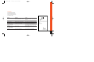
3. If you are running the amp in tri-mode
(stereo and mono simultaneously to
one or two pairs of satellite speakers
and a subwoofer), refer to the chart
above to determine the capacitor and
inductor values you’ll need to route
bass signals to the woofer, and
midrange and high frequencies to the
satellite speakers. These passive
crossover components will also ensure
that the impedance of the speaker sys-
tem doesn’t drop below 2 ohms.
(Fig. 7)
Wiring the Input Connections
1. If you are using conventional RCA
input connections and a source unit
with output voltage less than 4V, sim-
ply plug the RCA plugs into the RCA
jacks on the amplifier.
2. If you are connecting the amplifier to
a factory-installed source unit, or to a
source unit that only has speaker-level
outputs, connect the speaker outputs
of the source to the speaker inputs on
the amp, observing the following color
codes:
Front Left+: White
Front Left–: White with black stripe
Front Right+: Gray
Front Right–: Gray with black stripe
Rear Left+: Green
Rear Left–: Green with black stripe
Rear Right+: Purple
Rear Right–: Purple with black stripe
(Note: When using the Universal
Interface speaker-level inputs and line-
level outputs, the Rem terminal on the
amplifier may be used as a remote out-
put connection, and will provide power
to turn on other amplifiers and proces-
sors in the system.)
3. If you are connecting your Power
Series amplifier to a source unit with
output voltage higher than 4V, connect
the output-signal wires of the source
unit to the Universal Interface speaker
inputs. Because the inputs have an
impedance of 10K ohms, this connec-
tion will provide the best noise-free
performance possible.
FREQUENCY INDUCTOR CAPACITOR
Crossover 6dB/oct. LP 6dB/oct. HP
(4 ohm) (4 ohm)
75Hz 8.0mH 530µF
100Hz 6.4mH 400µF
125Hz 5.0mH 318µF
150Hz 4.2mH 265µF
175Hz 3.6mH 227µF
200Hz 3.2mH 198µF
P-4020/4040 OM. 7/14/98 11:42 AM Page 4