


CAUTION
I
nstallers must adhere to local building
c
odes to ensure proper installation.
JBL is not responsible for any possible
damage caused by improper installation.
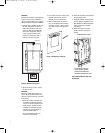
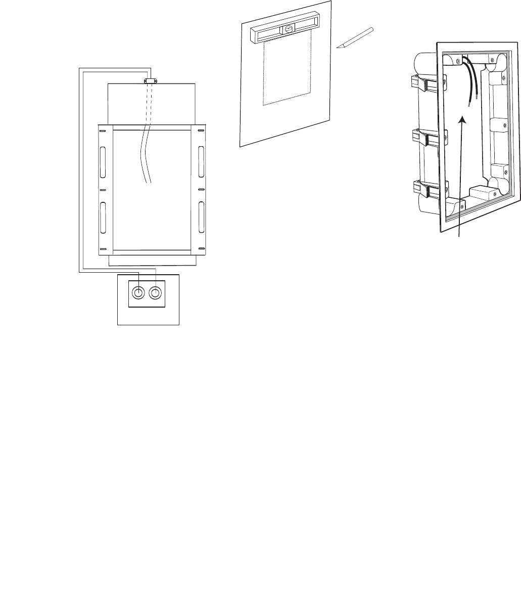
4
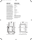
. Feed the power amplifier wires from
t
he wall cavity down through the
cable clamp located on top of the
enclosure. Pull approximately two
feet of wire through the clamp to
c
reate a generous service loop
inside the enclosure for ease of
hookup, as shown in Figure 6.
Figure 6: Amplifier Connections
5.
Tighten the clamp screws, cinching
the wires in place
.
CAUTION
Be sure to comply with local wiring
codes. JBL is not responsible for any
damage or injuries that may result from
faulty wiring.
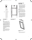
6.
Place the section of drywall over
the back box. With tape measure
and pencil, carefully measure and
mark where to position the wall
template (included with the loud-
speaker) by using the measure-
ments recorded in Step 1.
7.
Use the wall template to trace
where to cut the drywall.
8. Cut a small hole in the center of the
t
emplate area to make sure the
t
emplate is in the right location.
9. After confirming the correct loca-
tion, cut the template hole opening,
a
s shown in Figure 7. Use a carpen-
t
er’s level to ensure the opening is
level.
Figure 7: Cut Opening in Drywall
10. Fasten the drywall to the wall studs
u
sing drywall screws.
11. Install the speaker mounting frame
into the wall opening. Refer to the
JBL P81/P941 In-Wall Loudspeaker
o
wner’s manual for complete
i
nstructions.
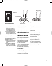
12. Route wires to the top of the
speaker frame to prepare for
h
ookup.
Figure 8: Route Wires to Top of the
Loudspeaker
I
n-Wall Speaker Frame
Route Wires to the Top
of the Speaker System
Avoid Contact Between
the Wires and Speaker Cone
B
ack Box
Cable Clamp
+
–
Binding Posts
Power Amplifier
6
P81BB, P941BB OM 11/16/05 3:04 PM Page 6