


3
ENGLISH
www.jbl.com
Impedance =
1
w
1
+
1
w
2
+
1
w
3
...
1
where w is the nominal impedance of the woofer.
2. The total system impedance of voice coils (or woofers) in series can
be calculated using this formula:
Impedance = w
1
+ w
2
+ w
3
...
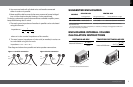
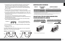
Tthe diagrams below show parallel and series speaker connections.
RED
POS (+)
POS (+)
FROM AMPLIFIER
Figure 1: Parallel connection
RED
POS (+)
POS (+)
FROM AMPLIFIER
NEG (–)
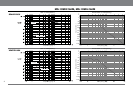
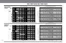
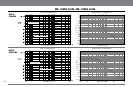
SUGGESTED ENCLOSURES
MODELS
Internal Volume Internal Volume Qty. Duct(s) Diameter x Length
MS-10SD2 SLIM
0.5 ft
3
(15l) 1 ft
3
(28l) 1 3 in x 7 in (7.5cm x 17.75cm)
MS-10SD4 SLIM
0.5 ft
3
(15l) 1 ft
3
(28l) 1 3 in x 7 in (7.5cm x 17.75cm)
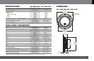
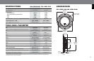
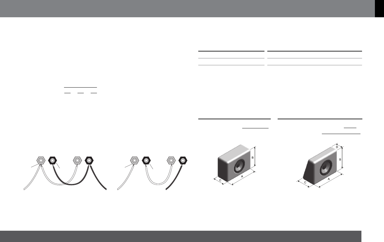
ENCLOSURES INTERNAL VOLUME
CALCULATION INSTRUCTIONS
TRAPEZOID RECTANGULAR BOX
Internal Volume =
A x B x C
1000
A x B x
(
C + D
)
1000
2
Internal Volume =
– A, B and C are internal dimensions.
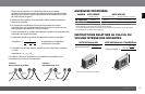
2. You must use both coils of a dual voice-coil woofer connected
either in series or in parallel.
3. Most amplifiers deliver exactly the same amount of power bridged
into a 4-ohm load as they do running a 2-ohm stereo load.
To design a subwoofer system that maximizes available amplifier power,
keep the following rules in mind:
1. The total system impedance of woofers in parallel can be calculated
using this formula:
Figure 2: Series connection
BLACK
NEG (–)
NEG (–)
BLACK
NEG (–)
SEALED BOX
VENTED BOX
– The suggested enclosure volumes are related to only one speaker, including woofer and duct(s)
displaced volume.
– For enclosures with more than one speaker, it is necessary to multiply the suggested volume and
duct(s) by the quantity of speakers.
RECTANGULAR BOX