


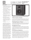

᭤ LSR6328P Linear Spatial Reference Bi-amplified Studio Monitor
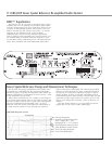
RMC™ Equalization
Through the use of a test CD, sound level meter and Q
template, the user can identify any dominant room mode
over the tuning range from 26 to 96 Hz that effects the LF
response at the listening position. The inverse curve can
then be entered into the system’s electronics – to exactly
compensate the offending peak. Using the RMC
Calibration Kit*, the user is also instructed specifically
what to look for, and potentially poor room locations can
be avoided. RMC kit contains all items required to carry
out the RMC system calibration process. *(Purchased sepa-
rately. Kit is included with each LSR6312SP Subwoofer)
We all know that many loudspeakers have similar mea-
surements but sound different. By going beyond simple
on-axis frequency response measurements, JBL defines the
ultimate performance specification for new systems – what
it will sound like in your room.
While other manufacturers use a single on-axis frequen-
cy response measurement taken at one point in space, JBL
measures monitor systems over a sphere that encompasses
all power radiated into the listening room – in every
direction. This data reflects 1296 times the information of
a single on-axis response curve. Seventy-two measure-
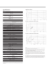
LSR6328P Response Curves
ments of the direct sound field, the reflected sound field,
and the reverberant field, the entire sound field heard by
the listener, is correlated to optimize response at the lis-
tening position. In place of spectral smoothing used by
some manufacturers, which actually conceals data, the JBL
approach actually exposes flaws in systems, such as reso-
nances, poor dispersion and other causes of off-axis col-
oration.
The data shown below is a set of spatially measured
graphs that are the heart of JBL’s philosophy.
Linear Spatial Reference Design and Measurement Techniques
3019665
Conforms to UL STD
6500, Certified to CSA
STD E60065
1. On-Axis Response
2. Spatially Averaged Response
over a range of +/- 30°
Horizontal & +/- 15° Vertical
3. First Reflection Sound Power
4. Total Radiated Sound Power
5. DI of On-Axis Response
6. DI of First Reflections