


4
5
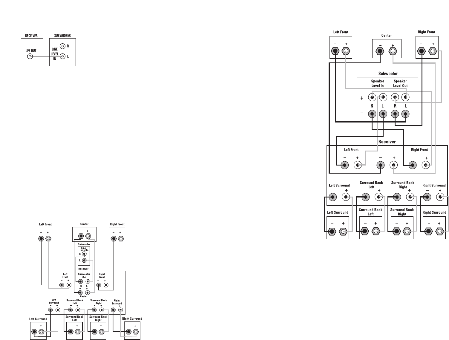
DOLBY PRO LOGIC (NON-DIGITAL)
–
SPEAKER LEVEL
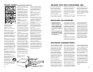
Use this installation method
for Dolby Pro Logic applica-
tions (not Dolby Digital, DTS
or other digital processing),
where the receiver/processor
does not have a subwoofer
output, or a volume-controlled
preamp (line-) level output:
Connect your receiver or
amplifier’s front left and right
speaker terminals to the left
and right terminals on the
subwoofer that are marked
“Speaker Level In.” Connect
the left and right terminals
on the subwoofer that are
marked “Speaker Level Out” to
the corresponding terminals on
the back of your front left and
right speakers.
Connect your receiver or
amplifier’s center, surround
and surround back speaker
terminals to the corresponding
terminals on the back of
your center and surround
speakers.
DOLBY PRO LOGIC
®
(NON-DIGITAL)
–
LINE LEVEL
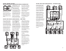
Use this installation method
for Dolby Pro Logic applica-
tions (not Dolby Digital, DTS
or other digital processing),
where the receiver/processor
is equipped with a subwoofer
output, or a volume-controlled
preamp (line-) level output:
Use RCA-type interconnects
to connect the line-level
subwoofer outputs on your
receiver or amplifier to the
line-level inputs on the sub-
woofer. IMPORTANT: Make
sure that the LFE/Normal
toggle switch ∞ is in the
“Normal” position. This will
activate the subwoofer’s low-
pass filter, protecting the sub-
woofer from possible damage
and enabling it to operate most
efficiently by reproducing only
the low-frequency materials
that it is best at handling.
NOTE: If your receiver or
amplifier only has one sub-
woofer output jack, then you
will need to use a Y-connector
(not included). Plug the male
end of the Y-connector into
your receiver or amplifier’s
subwoofer output jack, and
connect each of the two
female ends to separate RCA-
type interconnects. Finally,
plug the RCA-type intercon-
nects into the line-level inputs
on the subwoofer.
Connect each speaker to
the corresponding speaker
terminals on your receiver
or amplifier.
Make sure your receiver or
processor is correctly config-
ured to indicate that the sub-
woofer is “On.”
Note for advanced users: If
your receiver/processor has
a built-in low-pass crossover
filter for the subwoofer output,
you may switch the LFE/
Normal toggle switch to the
“LFE” position to bypass the
subwoofer’s internal
crossover.
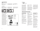
Use this installation method for
Dolby Digital, DTS or other dig-
ital surround processors:
Use either the left or right line-
level input jack for the Low-
Frequency Effects channel; it
doesn’t matter which one you
choose.
IMPORTANT: Make sure that
the LFE/Normal toggle switch
∞ is in the “LFE” position.
This will bypass the sub-
woofer’s normal low-pass
filter, reducing the possibility
of signal degradation and more
accurately reproducing the
program materials. However, if
your receiver is passing a full-
range signal through its sub-
woofer output, place the tog-
gle switch in the “Normal”
position, which will activate
the low-pass filter and protect
the subwoofer from possible
damage. Connect this jack to
the LFE output or subwoofer
output on your receiver or
amplifier. Connect each
speaker to the corresponding
speaker terminals on your
receiver or amplifier.
Make sure that you have con-
figured your surround sound
processor for “Subwoofer On.”
Also, remember to configure
your receiver for 5.1-, 6.1- or
7.1-channel operation as
appropriate.
DOLBY
®
DIGITAL OR DTS
®
(OR OTHER DIGITAL SURROUND MODE) CONNECTION