


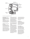


CHAPTER 7 – PROJECT K2 S5800 SWITCH OPERATIONS
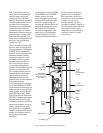
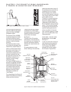
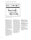
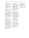
The K2 S5800 has two switches
mounted on the network panel
on the rear of the enclosure.
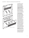
The switches are covered by
an access plate which is easily
removed by unscrewing the two
mounting screws. See Figure 8.
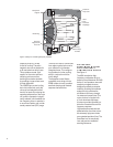
The
Network Mode (Bi-Amp)
Switch ™ (center) should be left in
the Normal position except when
bi-amplification with an external
electronic crossover is to be
employed. The necessary cross-
over slopes for the K2 S5800 are
very specific and bi-amping the sys-
tem should only be done using fac-
tory-approved electronics.
The
HF Trim Switch £ (right)
adjusts the high-frequency level
over the range of approximately
1000Hz to 10kHz. The +1dB position
gives the highest HF output and
measures the most level. 0dB
reduces the HF level by 1dB and
the –1dB position reduces the HF
level by an additional 1dB.
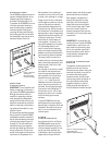
Although the range of these con-
trols is rather small, each of them
operate over a reasonably wide
frequency range and thus have a
noticeable effect on the overall
tonal balance of the system. It is
recommended that the system first
be played with the switch in the
middle position. This setting gives
the most uniform measurements
in a controlled environment. Of
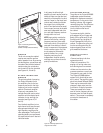
course, we are interested in pro-
ducing the most pleasing sound in
your environment with your choice
of program material. It is, therefore,
recommended that the
HF Trim
Switch
£ be tested in its various
settings on a variety of program
material. Once you become familiar
with their individual character, you
should have no difficulty determin-
ing the setting which produces the
most pleasing, natural sound in
your room with your equipment.
B
I-A
M
P
N
O
R
M
A
L/
B
I-W
IR
E
+1dB
0dB
-1dB
HIGH FREQUENCY TRIM
J
B
L
IN
C
O
R
P
O
R
A
T
E
D
8
5
0
0
B
a
lb
o
a
B
lv
d
. N
o
rth
rid
g
e
, C
A
U
S
A
H
ig
h
F
re
q
u
e
n
c
y
L
o
w
F
re
q
u
e
n
c
y
K2 S5800
JBL INCORPORATED
8500 Balboa Blvd. Northridge, CA USA
High Frequency
Low Frequency
K2 S5800
Figure 8. Access to control panel.
13