


CONTRÔLE, CONNEXION ET VOYANTS
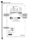
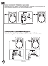
1. OUTPUT A & OUTPUT B CONNECTORS - OUTPUTS A & B provide either a loop-thru or a high-passed, line level output of
the signal from the INPUT A and INPUT B connectors respectively. These connectors work with the OUTPUTS A & B switch.
2. INPUT A & INPUT B CONNECTORS - These electronically balanced, XLR / 1/4" phone "combi" connectors accept input signal
from line-level sources. a.) INPUT A and INPUT B are combined before being routed to the JRX118SP Low Pass Filter (LPF) and
internal amplifier. b.) INPUT A and INPUT B are also routed to the OUTPUT A and OUTPUT B connectors (see OUTPUTS A & B
SWITCH below).
3. SPKR LEVEL IN - This 1/4" phone jack allows connecting of the speaker level output of an amplifier or powered mixer to the
JRX118SP internal amplifier.
4. SUB LEVEL CONTROL - Adjusts the input sensitivity of the subwoofer amplifier. Does not affect OUTPUTS A & B.
5. SIGNAL - Lights to indicate that a signal is present at INPUT A, INPUT B or the SPKR LEVEL IN.
6. LIMIT - Lights to indicate that the limiter circuitry has been activated. In normal operation, this light will flicker on and off. If the
LIMIT light is lit continuously, it indicates that the amplifier is being driven too hard and that the volume should be reduced.
7. OUTPUTS A & B SWITCH - This switch affects the signal sent to the OUTPUT A & B connectors. a.) THRU: The INPUT A signal
is passed directly to the OUTPUT A connector and the INPUT B signal is passed directly to the OUTPUT B connector. b.) HPF: The
INPUT A signal is first passed through a 120 Hz, -6 dB High Pass Filter (HPF) before being sent to the OUTPUT A connector. The
INPUT B signal is first passed through another 120 Hz, -6 dB High Pass Filter (HPF) before being sent to OUTPUT B connector.
8. SUB POLARITY SWITCH - This switch changes the polarity (sometimes called "phase") of the subwoofer.
9. POWER SWITCH - Turns the AC power of the unit on and off. The switch illuminates to indicate that the unit is on.
10. AC INPUT - For attachment of the included power cable.
CONTROLS, CONNECTORS AND INDICACTORS
1. OUTPUT A & OUTPUT B CONNECTEURS - SORTIES A & B du signal au niveau ligne, commute la sélection des signaux
d'entrées INPUT A et INPUT B (large bande) ou filtrage des entrées par filtre passe Haut
2. INPUT A et INPUT B CONNECTEURS - Ces sorties symétriques sur combo XLR / Jack 6,35 acceptent des entrées de sig-
naux aux niveaux ligne. a.) La somme des entrées INPUT A et INPUT B est acheminée au filtre passe Bas du JRX118SP puis a
l'amplificateur intégré. b.) Les entrées INPUT A et INPUT B sont parallèlement disponibles sur les sorties OUTPUT A et OUTPUT B
(voir OUTPUTS A & B commutateur ci-dessous).
3. SPKR LEVEL IN - cette entrée jack 6,35 permet la connexion d'un signal en provenance d'un amplificateur ou de la sortie d'un
mélangeur amplifié.
4. SUB LEVEL CONTROL - Ajuste la sensibilité du niveau d'entrée de l'amplificateur indépendamment des sorties Outputs A et
Ouputs B.
5. SIGNAL - Ce voyant indique la présence d'un signal aux bornes d'entrées INPUT A, INPUT B ou SPKR LEVEL IN.
6. LIMIT - Ce voyant indique que le limiteur est actif. Ce voyant clignote durant le fonctionnement normal de l'appareil. Si le voyant
reste allumé de façon continue le limiteur fonctionne sans interruption (L'amplificateur reçoit un signal trop élevé), Il est conseillé de
réduire le niveau d'entrée.
7. OUTPUTS A & B SWITCH - Ce commutateur sélectionne le signal transmis aux bornes OUTPUT A & B. a.) THRU: Le Signal
présent a la borne d'entrée INPUT A est transmis directement aux bornes de sortie OUTPUT A . Le signal présent aux bornes
d'entrée INPUT B est transmis directement aux bornes de sortie OUTPUT B. b.) HPF: Le signal présent aux bornes d'entrée INPUT
A, passe au travers d'un filtre passé haut 120 Hz, -6 dB puis est disponible aux bornes de sortie OUTPUT A. Le signal présent aux
bornes d'entrée INPUT B passe au travers d'un autre filtre Passe haut 120 Hz, -6 dB avant d'être disponible aux bornes de sortie
OUTPUT B.
8. SUB POLARITY SWITCH - Permet de changer la polarité (ou phase )du subwoofer.
9. POWER SWITCH - Mise sous tension de l'appareil. Le voyant s'allume lorsque l'appareil est sous tension.
10.AC INPUT - permet le raccordement du cordon d'alimentation électrique fourni avec l'appareil.
(Refer to Panel Call Out Drawing on page 14)
(Voir Nomenclature des panneaux page 14)
1122