


3
1. Introduction
1.1 Thanks for purchasing your new
GT series automotive multi-channel
amplifier. Your GT series amplifier will
easily connect to virtually any car audio
system, whether it is factory installed or
purchased separately. The GTQ360 and
GTQ240 include an abundance of unique
features which are described in this man-
ual. The flexible design of their built-in
crossover circuitry allows elaborate sys-
tems to be built more simply than with
conventional components. For optimum
performance, the power amplifier circuit-
ry is a fully-discrete design notable for its
low distortion and unusually clean and
clear sound quality.
In addition to conventional preamp-level
inputs, the GTQ360 and GTQ240 feature
JBL’s Universal Interface™ design, which
facilitates simple connection to factory
radios with the low distortion that is usu-
ally only associated with preamp level
connection. With the Universal Interface
on the GTQ360 and GTQ240, a factory
radio can either be used as the main
music source or simultaneously com-
bined with a CD player or changer that
has volume-control capability. By provid-
ing this two-unit direct connection,
Universal Interface circuitry eliminates the
need for an FM modulator to interface a
CD player to factory radios, improving the
fidelity of digital playback.
In addition, when using a high-powered
(BTL) radio through the speaker-level
inputs, Common Sense turn-on circuitry
senses the common-mode voltage pres-
ent on the radio’s speaker wires, turning
the amplifier on without an additional
remote wire.
Also, the built-in active cross-over pro-
vides either full-range, high-pass or low-
pass operation. This lets your GT series
amplifier power either subwoofer or com-
ponent speakers in a bi-amplified system,
or conventional full-range speakers in
simpler systems.
The GTQ360 and GTQ240 also include
preamp-level outputs which can provide
either full-range, high-pass or low-pass
signal to drive additional amplifiers. This
lets you build systems of virtually any
design without requiring a separate elec-
tronic crossover.
1.2 About Installation
Although the GTQ360 and GTQ240 are
designed to make installation as easy as
possible, these are extremely sophisticat-
ed products that require proper installa-
tion and setup to realize their full perfor-
mance potential. If you feel you do not
have the necessary knowledge and skills,
we strongly recommend that the installa-
tion be done by your authorized JBL deal-
er.
If you choose to install the GTQ amplifier
yourself, read all of the information in this
manual before you start the installation.
Pay particular attention to the safety pre-
cautions and notes.
2. Installation and Use
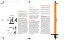
2.1 Refer to the “Speaker-Level Input
Impedance Adjustments” and “Crossover
Frequency Adjustments” sections of this
manual (page 7) to see if you will need to
make alterations to the factory settings. If
you are not using the built-in crossover,
or the speaker-level inputs, you may skip
this step.
1. Disconnect the negative cable from the
battery. Note: If the vehicle’s radio fea-
tures a code-type security system, make
certain you know the code before discon-
necting the battery!
2. Run a power cable complete with a
fuse (not included) directly from the posi-
tive +12V battery terminal to the desired
amplifier location. Keep the fuse within 6"
of the battery terminal, and position it
before the wire runs through any metal
partition. A minimum of #10AWG is
required for the GTQ240 and #8AWG for
the GTQ360. The GTQ240 requires a 30A
fuse, the GTQ360 a 60A fuse.
Note: All wiring connections should be
made either by soldering with heatshrink
tubing insulation, by using commercially
available high-quality distribution blocks,
or with high-quality crimp-type insulated
connectors installed with a professional-
type, articulated crimping tool. Soldering
crimp-type terminals is recommended for
additional security. Never use wire nuts,
insulation-displacement connectors (i.e.,
ScotchLok type), or twist and tape con-
nections. Do not use electrical tape; it will
loosen with age and extreme
temperatures.
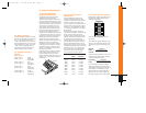
3. Mount amplifier in the desired location
using the included screws.
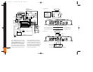
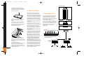
4. Connect power wiring as shown in the
Wiring Diagram.
5. Connect the outputs from the head unit
to the appropriate inputs of the amplifier
according to the Wiring Diagram with
either (or both) high-quality low-level sig-
nal cables with RCA plugs, or the supplied
speaker-level input connector.
6. Connect the speakers to the amplifier
according to the Wiring Diagram.
7. Turn the gain controls to the
1/4-position for all groups.
8. Set the bass boost of each group to the
desired position.
9. Set the crossover switches for each
group as desired.
10. Set the Group 2 Input as desired.
11. Set the mode switches to Stereo,
Left + Right, or Left Input Only operation
for each group.
12. Double-check your switch settings.
Reconnect the negative battery cable.
Note: Incorrect switch settings can dam-
age your speakers!
13. Turn on the signal source at a low vol-
ume level, and check for the correct out-
put from each speaker.
14. Adjust the amplifier gain controls
using the procedure described in the
“Adjusting the Gain” section.
15. Read the rest of the manual to get
maximum use and enjoyment from your
amplifier.
GTQ 360 new 7/17/98 10:44 AM Page 3