


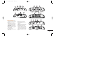

Applications
For your convenience, we’ve included
several application diagrams to help you
plan your own system installation.
Figures 1 through 4 show how to config-
ure the Decade Series power amplifiers
for stereo, bridged-mono and tri-mode
operation.
(Note: For simplicity, figures do not
show power, remote and input connec-
tions.)
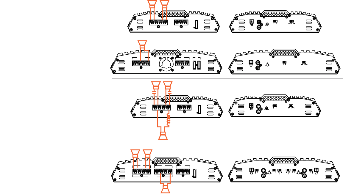
Figure 1. This wiring diagram shows a
DA4002, DA6502 amplifier set to stereo
to drive a pair of full-range speakers.
Figure 2.This wiring diagram shows a
DA1002 amplifier set to bridge mode
(mono) to drive a single subwoofer.
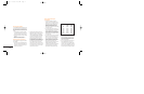
Figure 3.This wiring diagram shows a
DA4002, DA6502 amplifier set for tri-
mode operation. For a desired crossover
frequency, use the chart on page 4 to
select an inductor for the subwoofer,
and corresponding capacitors for left
and right speakers.
Figure 4.This wiring diagram shows a
DA3504 set to drive a pair of 5-1/4"
2-way speakers with the two front
channels, and the rear channels set
to drive a single subwoofer in bridge
mode.
6
SPEAKER OUTPUT
+
–
RIGHT
+
–
LEFT
+
–
POWER
REM GND(
–)BATT(+)
FUSE
BRIDGED
15 AMP
15
+
–
+
–
LEFT RIGHT
+
–
BRIDGED
SPEAKER OUTPUT
POWER
FUSE
20 AMP
REM GND(
–)BATT(+)
20
SPEAKER INPUT LINE INPUT
R
L
BASS EQ
INPUT
LEVEL
L
+
––
+
R
R
L
OFF
6dB
+
110
CROSSOVER
LPF HPFFLAT
SPEAKER OUTPUT
+
+
–
–
+
–
POWER
REM GND(
–)BATT(+)
BRIDGED
RIGHTLEFT
FUSE
20 AMP
20 AMP 20 AMP
20
20
L
L
+
+
–
–
+
–
R
R
R
+
–
SPEAKER INPUT LINE INPUT
R
L
110
BASS EQ
INPUT LEVEL
L
OFF
6dB
+
LOW PASS
FILTER
OFF 70Hz100Hz
SPEAKER INPUT
L
L
L
+
–
+
–
R
R
R
LINE INPUT
110
BASS EQ
INPUT
LEVEL
CROSS OVER
OFF
6dB
+
LPF HPFFLAT
+
–
+
–
+
–
REAR
LEFT RIGHT
+
–
+
–
LEFT RIGHT
BRIDGED
+
–
BRIDGED
SPEAKER OUTPUT
FRONT
POWER FUSE
30 AMP
REM GND(
–)BATT(+)
30
SPEAKER
INPUT
INPUT
MODE
SPEAKER
INPUT
INPUT
MODE
STEREO
MONO
L
+
–
R
+
–
LINE INPUT
R
L
110
BASS
EQ
BASS
EQ
INPUT
LEVEL
INPUT
LEVEL
CROSS
OVER
CROSS
OVER
OFF
6dB
+
OFF
6dB
+
LPF HPF
FLAT
LPF HPF
FLAT
110
LINE INPUT
R
L
STEREO
MONO
L
–
–
R
+
–
Figure 1
Figure 2
Figure 3
Figure 4
DA OM 7/14/98 11:38 AM Page 6