


4
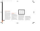
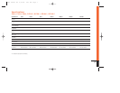
FREQUENCY INDUCTOR CAPACITOR
Crossover 6dB/oct. LP 6dB/oct. HP
(4-ohm) (4-ohm)
75Hz 8.0mH 530µF
100Hz 6.4mH 400µF
125Hz 5.0mH 318µF
150Hz 4.2mH 265µF
175Hz 3.6mH 227µF
200Hz 3.2mH 198µF
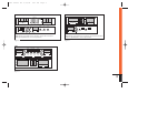
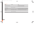
Wiring the Power Connections
Refer to Figures 1–3 for connector loca-
tions. All the Power Series amplifiers
will accept up to 4-gauge power and
ground wire.
For power, remote and ground connec-
tions, strip off one end of each jacket to
reveal bare wire for insertion into the
connectors. Connect a wire from the
GND connector on the amplifier to the
nearest bare-metal chassis component;
scrape away the paint to ensure good
conductivity. Next, connect a wire
between the BATT terminal on the
amplifier and the POS(+) terminal of the
vehicle’s battery. Pass the wire through a
factory-installed grommet in the firewall,
or install a grommet if a factory grom-
met is not available. Connect a wire
between the REM terminal of the ampli-
fier and the “remote out” or power-
antenna lead on the vehicle’s radio.
Wiring the Speaker-Output
Connections
P80.2, P180.2, P80.4
All the Power Series amplifiers will
accept up to 8-gauge speaker wire.
Connect the speakers, observing proper
polarity, to the speaker-output connector.
The total impedance of the speaker
system connected to the amplifier when
the amplifier is driven in stereo must be
at least two ohms.
If you are bridging the amplifier, connect
the speaker wires to the terminals
marked “bridged,” observing proper
polarity. The total impedance of the
speaker system connected to the amplifi-
er must be at least four ohms in bridged
mode.
If you are running the amp in Tri-Mode
(stereo and mono simultaneously), con-
nect the satellite speakers to the speaker
connector as you would a pair of stereo
speakers. Connect the subwoofer to the
terminals marked “bridged” Refer to the
chart above to determine the capacitor
and inductor values you’ll need to route
bass signals to the woofer, and the
midrange and high frequencies to the
satellite speakers. These passive
crossover components will also ensure
that the impedance of the speaker sys-
tem doesn’t drop below two ohms.
BP150.1, BP300.1, BP600.1, BP1200.1
Connect the woofers to the amplifier,
observing proper polarity. Although
these amplifiers have a single channel,
duplicate positive and negative connec-
tors are provided to facilitate the connec-
tion of multiple woofers.
The total impedance of the speaker
system connected to a BP Series
amplifier must be at least 1 ohm.
Power Series OM 4/15/99 9:17 AM Page 4