5
4
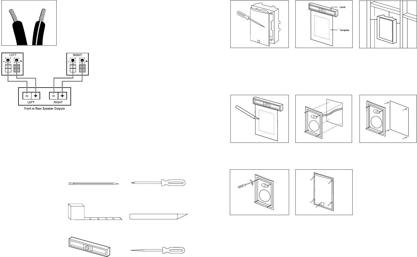
Phillips #2 screwdriver
Measuring tape
Utility knife
Pencil
Carpenter’s level
Awl
TOOLS NEEDED
SP5, SP6, SP8
The SoundPoint
™
Series in-wall
speakers were
designed to be
easily installed. However, if you
are unsure of your ability to prop-
erly install these loudspeakers,
please contact your dealer or a
qualified installer.
INSTALLATION
EXISTING CONSTRUCTION
Remove the grille from the
speaker frame.
Determine the correct speaker
location.
Note: Remove the inner template,
which is the paint shield, at the
perforation. Use the outer tem-
plate when cutting the drywall.
Note: Always allow at least
one-half inch between a wall
stud and the speaker cutout or
the locking tabs will not be able
to swivel into place.
≥1/2"
≥1/2"
≥1/2"
Cut the drywall.
Connect the speaker wires
to the speaker.
Speakers and electronics
terminals have corresponding
(+) and (–) terminals. Most
manufacturers of speakers and
electronics, including JBL, use
red to denote the (+) terminal
and black for the (–) terminal.
It is important to connect both
speakers identically: (+) on the
speaker to (+) on the amplifier
and (–) on the speaker to (–)
on the amplifier. Wiring “out
of phase” results in thin sound,
weak bass and a poor stereo
image. With the advent of multi-
channel surround-sound
systems, connecting all of the
speakers in your system with
the correct polarity remains
equally important in order to
preserve the proper ambience
and directionality of the
program material.
CONNECTION TIPS
WIRE LENGTH RECOMMENDED SIZE
Up to 20 ft. 16 gauge
Up to 30 ft. 12 gauge
Greater than 30 ft. 10 gauge
The wires for both speakers
should be the same length. If
one speaker is placed closer to
the amplifier than the other,
hide the excess wire behind
the wall.
SPEAKER CONNECTIONS
Replace the metal grille.
Place the frame assembly
in the wall.
Screw down each of the four
Phillips head screws. The
locking tabs will swivel into
place and secure the unit to
the rear surface of the drywall.
Soundpoint OM SP5-6-6C-8-8 5/20/02 2:06 PM Page 4


