


1400 ARRAY ASSEMBLY
Due to the weight of the
1400 Array horn module, it
is packed separately from
the low-frequency enclosure.
It is a very simple procedure
to install the module, and the
necessary instructions are
listed below. The required
Allen-tipped screw driver is
included in the accessory
pack.
1. Carefully remove the horn
module from the packaging
and place it face down on a
soft surface.
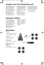
2. Locate the cardboard
accessory sleeve and
remove the hardware.
3. The accessory sleeve
should contain:
a. 2 Long 1/4" x 20 Allen-
head bolts
b. 1 Short 1/4" x 20 Allen-
head bolt
c. 1 Logo plate
d. 1 Rubber hole plug
e. 4 Metal coasters
(to protect wood and tile
floors from the spike feet)
4. Carefully unpack the low-
frequency enclosure and
place it upright. It would be
helpful to position it near its
final position in the room
since it is much easier to
move without the additional
weight of the horn module.
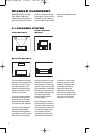
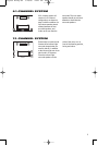
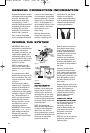
5. Notice the two threaded
inserts on the angled face
of the top and also the small
L-bracket on the top. These
are the attachment points
for the horn module. Imme-
diately adjacent to the L-
bracket is a recessed con-
nector which will make the
electrical connection for the
horn module.
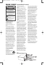
6. Although the module can
be installed by one person,
it is easier if a second set
of hands are available.
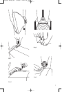
7. Cradle the horn module with
the opening along your fore-
arm and, using your free
hand, connect the plug
coming from the bottom of
the horn assembly into the
jack on the top of the
enclosure.
8. You can now place the horn
in position on top of the
enclosure. The L-bracket
fits in an opening under the
horn assembly. The module
will sit on top of the enclo-
sure by itself, although it
should always be steadied
until fully mounted.
9. Line up the two mounting
holes on the lower lip of the
front of the horn with those
in the enclosure. Partially
install one long bolt and
then the other one. It may
be necessary to lift the horn
slightly so that the bolts
install smoothly. Do not
force or cross-thread them.
10. Once both bolts have been
started, work them in all of
the way, but do not tighten
them securely just yet.
11. Install the remaining short
bolt in the hole at the
bottom rear of the horn
module. You can fully
tighten this bolt.
12. Now completely tighten the
two front bolts.
13. Everything should be tight
and properly aligned at this
time. If not, loosen, realign,
and retighten as required.
14. The final steps are to
remove the backing from
the logo badge and place it
in the recess on the lower
horn lip, and to use the
rubber hole plug to hide the
hole at the bottom rear of
the horn module. Do not
complete these steps until
the system has been turned
on and tested acoustically.
Make sure the horn module
is playing first. Once the
logo badge and rubber
plug hole are installed, it
is extremely difficult to
remove them.
6
Project Array OM 1/10/06 12:21 PM Page 6