


8
LA-2A Block Diagram
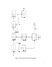
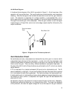
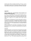
A functional block diagram of the LA-2A is provided in Figure 3. A brief overview of the
operation will be provided here. The input transformer provides isolation and impedance
matching. After this the signal is fed into both the side-chain circuit and the gain reduction
circuit. The side-chain is comprised of a voltage amplifier, a pre-emphasis filter, and a
driver stage which provides the voltage necessary to drive the electro-luminescent panel.
This signal controls the gain of the compressor. After the gain reduction circuit, the signal
is sent through an Output Gain control and a two-stage output amplifier, followed by the
output transformer.
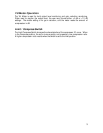
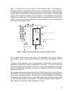
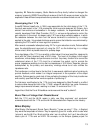
Electro-luminescent
Panel
Photo-Electric Cell
Figure 4 - Diagram of the T4 electro-optical cell.
Gain Reduction Circuit
As mentioned previously, compressors are devices that vary their gain in a manner which
is dependent upon the level of the input signal. In order to do this, the compressor must
first have some method of determining the level of the signal, and must then be able to use
this to control the gain. There are many different schemes to accomplish these tasks. In
the case of the LA-2A, both of these functions are performed by the T4, which is an electro-
optical element.
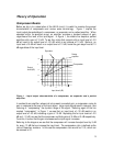
A T4 is comprised of an electro-luminescent (EL) panel and a photo-electric cell. The EL
panel is essentially a night-light. As you would expect, the larger the signal that is applied
to it, the brighter the light that is generated. This light shines upon the photo-electric cell.
A photo-electric cell is a light sensitive device whose resistance changes depending upon
the intensity of light to which it is subjected; the brighter the light, the less resistance the
photo-cell will have.
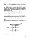
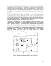
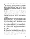
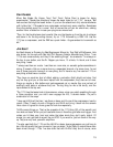
As depicted in Figure 5, the photo-cell is used to control the gain of the circuit. Essentially,
the photo-cell acts as the bottom leg in a voltage divider circuit. The lower the resistance
of the photo-cell, the lower the signal voltage will be at the output of the gain reduction