


IMPORTANT!
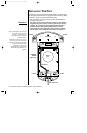
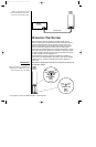
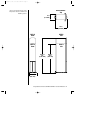
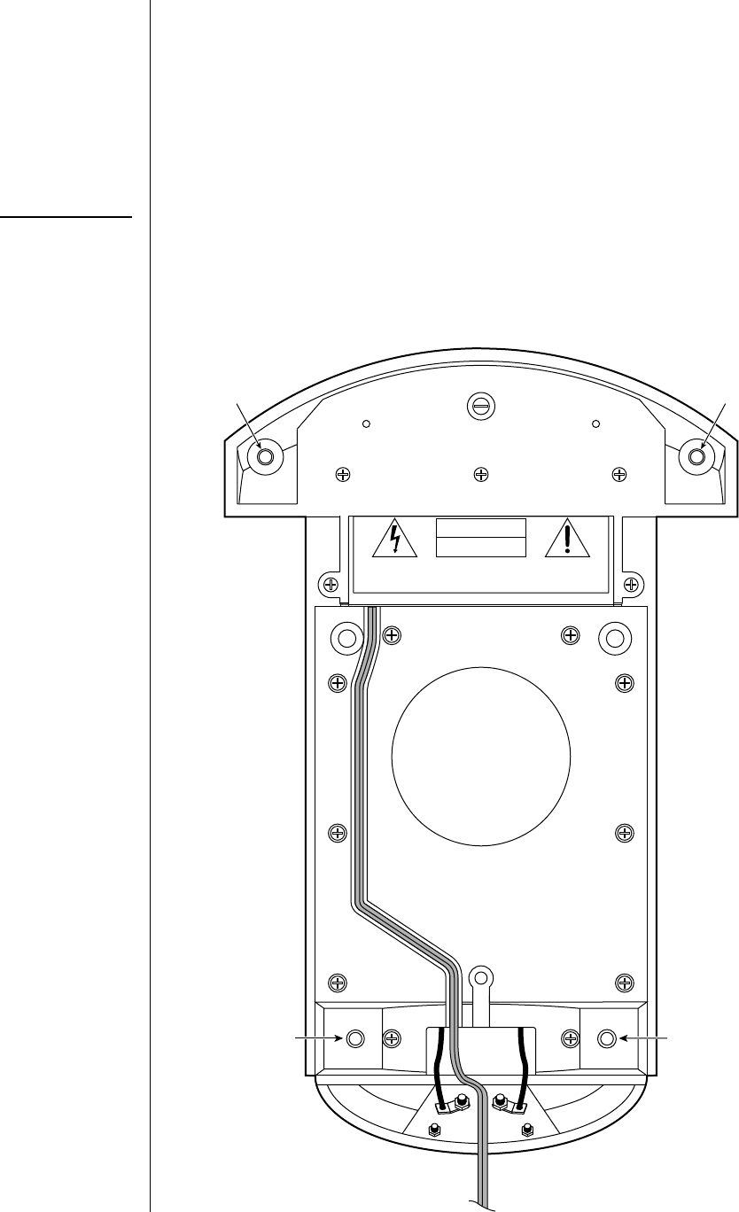
Figure 1. This bottom view shows the
four locations of the foot holes
and the ac cord channel on a
Compositions Overture OVTR 2
or OVTR 3 speaker.
NOTE: Do not unfasten any screws.
There are no user-serviceable parts
inside the speaker. For service, please
contact an authorized Infinity
technician for help (also see
“Troubleshooting” on page 8 and
“Limited Five-Year Warranty” on
page 12).
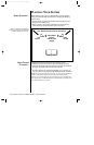
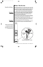
INSTALLING THE FEET
Compositions Overture OVTR 2 and OVTR 3 speakers use dual-purpose
feet with spike and round ends for carpeted or hard-surface floors. Refer
to Figures 1 and 2 as you perform the following steps:
1. Lay each speaker on its side and locate the four threaded holes on
the bottom (see Figure 1).
For safety reasons, each speaker base contains a cord channel
designed to keep the ac power cord away from the feet. During
shipping, the cord may become dislodged from its intended
position and upon subsequent speaker placement may be
accidentally pierced by spiked feet. Please make sure that the
120 Vac power cord is inside the cord channel (see Figure 1).
2
◆
Compositions Overture OVTR 2/OVTR 3 – Owner’s Manual
~120V 60Hz
300W MAX
CAUTION
RISK OF ELECTRIC SHOCK
DO NOT OPEN
AVIS: RISQUE DE CHOC ELECTRIQUE - NE PAS OUVRIR
CAUTION:
FOR CONTINUED PROTECTION AGAINST
RISK OF FIRE, REPLACE ONLY WITH SAME
TYPE OF FUSE: 2AG SB 250V
ATTENTION:
UTILSER UN FUSIBLE DE
RECHANGE DE MEME
TYPE ET CALIBRE
F
U
S
E
F
U
S
E
Foot HoleFoot Hole
Fuse Holder
OVTR 2 or
OVTR 3
(bottom view)
Foot HoleFoot Hole
120 Vac Power Cord
Cord Channel
Speaker
Port
Overture 2/3 Ins 9/11/98 4:23 PM Page 2