


- 2 -
ABOUT THESE INSTRUCTIONS
Installation of automotive stereo components
can require extensive experience with a variety
of mechanical and electrical procedures. Although
these instructions explain how to install Kappa
Series Component Systems in a general sense, they
do not show the exact installation methods for your
particular vehicle. If you do not feel you have the
experience, do not attempt the installation yourself,
but instead ask your authorized Infinity car audio
dealer about professional installation options.
LOUD MUSIC AND HEARING
Playing loud music in an automobile can hinder
your ability to hear traffic, as well as permanently
damage your hearing. The maximum volume lev-
els achievable with Infinity speakers, combined
with high power amplification, may exceed safe
levels for extended listening. We recommend
using low volume levels when driving. Infinity
accepts no liability for hearing loss, bodily injury,
or property damage as a result of use or misuse
of this product.
REAR DECK PRECAUTION
In some cars, fuel tanks may be located directly
beneath the rear deck. Before installation, make
sure there is adequate speaker basket clearance
before considering this location!
ABOUT THE CONTENTS
The Kappa Component System includes:
•5-1⁄4" or 6-1⁄2" or 165mm woofer
• Grille and mounting adapter(s)
• 1" tweeter with surface/flush I-Mount™
(patent no. 5,859,917) kits
• Crossover network with mounting screws
NOTE:The supplied crossover network is designed
to work with the above-listed transducers. Do not
substitute another crossover network or use other
speakers when connecting the system
(see Figure 7A).
INSTALLATION TIPS
• Always wear protective eyewear when using
any tools.
•Turn off all audio components and other
electrical devices before you start. Disconnect
the (–) negative lead from your vehicle’s battery.
•Keep speakers in their package until final
installation. When moving a speaker, always
rest it with the cone or dome facing up. Never
use force to install any speaker.
• Check clearances on both sides of a planned
mounting surface before drilling any holes or
installing any screws. Remember that the
screws can extend behind the surface.
• At the installation sites, locate and make a
note of all fuel lines, hydraulic brake lines,
vacuum lines and electrical wiring. Use
extreme caution when cutting or drilling
in and around these areas.
• Before drilling or cutting holes, use a utility
knife to remove unwanted fabric or vinyl,
to keep material from snagging in a drill
bit or saw.
•For door installations, check the clearance
with the windows throughout the range of the
window’s travel, and verify that a mounted
speaker will not interfere with the window
crank or power window mechanism.
• If mounting speakers elsewhere, check for
clearance around rear deck torsion bars,
glove box or other structural elements.
• Do not mount speakers where they will get wet.
• If possible, select a mounting site for the
crossover network that is near the speakers
and provides easy access for connections.
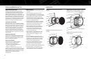
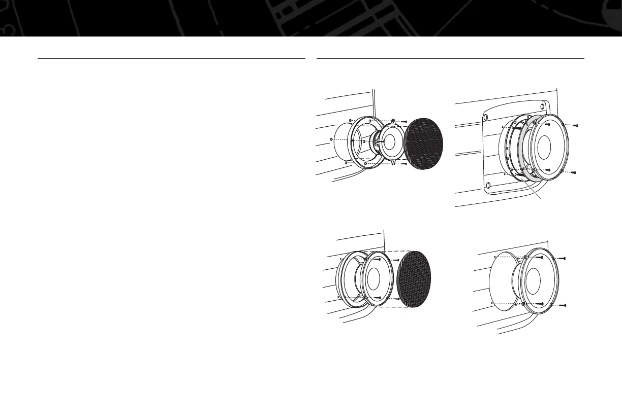
Figure 1. Mounting the 50.5cs woofer with
the grille.
Figure 2. Mounting the 60.5cs woofer with
the grille.
Figure 3. Mounting the 60.5cs woofer in a standard
speaker location. A variety of adapter rings are
supplied to fit many installation configurations.
Figure 4. Mounting the 65.5cs ina 165mm
speaker location.
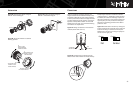
INSTALLATION WARNINGS AND TIPS
INSTALLATION
ADAPTER RING(S)