


T498A,B ELECTRIC HEAT THERMOSTATS
95C-10686—3
4
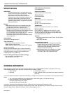
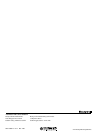
Fig. 4. Locking cover installation.
4
0
5
0
6
0
7
0
8
0
OFF
°F
50 60 70 80 90
M7236
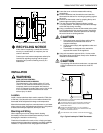
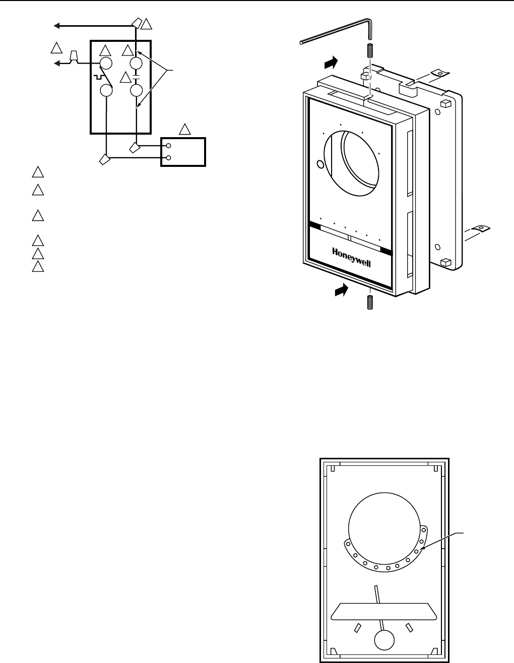
Range Stops
ᕡ Set the thermostat to the desired setpoint. Remove the
cover.
ᕢ Install the plastic dowels (included) into the minimum
and/or maximum range stop holes on the inside back of
the cover. See Fig. 5.
ᕣ Replace the cover. Check the operation of the range
stops.
RANGE STOP
HOLES
M7238
Fig. 5. Range stop installation.
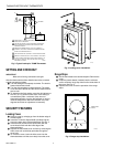
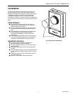
M6092A
ELECTRIC
HEATER
T1
L1
T2
L2
L1
(HOT)
L2
1
POWER SUPPLY. PROVIDE DISCONNECT MEANS AND OVERLOAD
PROTECTION AS REQUIRED.
USE SPECIAL SERVICE CO/ALR SOLDERLESS CONNECTORS
WHEN CONNECTING ALUMINUM CONDUCTORS OR A FIRE
HAZARD MAY RESULT.
BREAKS AND REMAKES BELOW -31°F(-35°C); NORMALLY
THERMALLY ACTIVATED. BREAKS ON A TEMPERATURE RISE;
MAKES ON A TEMPERATURE FALL.
USE A SEPARATE LIMIT CONTROL IN THE HEATING APPLIANCE.
BREAKS AT POSITIVE OFF ONLY; NOT THERMALLY ACTIVATED.
DO NOT CONNECT GROUNDED CONDUCTORS (NEUTRAL) ON
120V OR 277V CIRCUITS. INSULATE AND TAPE, OR CUT OFF
RED WIRES IF UNUSED.
1
2
3
4
5
5
6
6
3
2
4
T498B
RED WIRE
Fig. 3. Typical hookup for T498B Thermostat.
SETTING AND CHECKOUT
IMPORTANT
Make sure all wiring connections are tight.
After the thermostat has been installed and wired, simulate
normal operation as follows.
ᕡ Turn the setting dial completely clockwise. The electric
heater should start to heat.
ᕢ Turn the dial completely counterclockwise. The power
circuit should be broken and the electric heater should
start to cool.
ᕣ To determine the final setting, move the dial indicator to
the 70°F (21°C) position on the scale. If the setting is
not satisfactory after a minimum of two hours of
thermostat operation, turn the dial indicator to raise or
lower the temperature. Move the indicator only a few
degrees each time an adjustment is necessary.
SECURITY FEATURES
Locking Cover
ᕡ Remove cover by swinging up from the bottom edge of
the thermostat.
ᕢ Insert the Tinnerman Speed Nut® (included) into the
slot on the lower back of thermostat base. See Fig. 4.
ᕣ Insert the Allen screw into the Speed Nut until the
screw head is flush with the lower edge of the
thermostat base.
ᕤ Replace the thermostat cover and lock by removing the
Allen screw until screw body protrudes through the
cover hole.
ᕥ To unlock the cover, insert the Allen screw into the
thermostat base until the screw body clears the cover.