


— 2 — — 3 —
3. If concealed wiring is to be used, feed the wires through the concealed wiring entry hole at
one corner of the plate (surface wiring is mentioned in Step 5 below).
4. Install the mounting plate, with its case holding posts pointing up (in this example), in the
location selected as described in the control unit’s installation instructions. Use the flat-head
screws supplied.
5. If concealed wiring is to be used, feed it through the slot in the case back but do not connect
to the terminal block yet. Surface wiring should enter via the thin "breakout" area provided in
the case wall.
6. Attach the case back to the mounting plate by sliding the keyhole slots in the case back down
onto the mounting plate’s hooks. The locking tab will click as the case back locks in place.
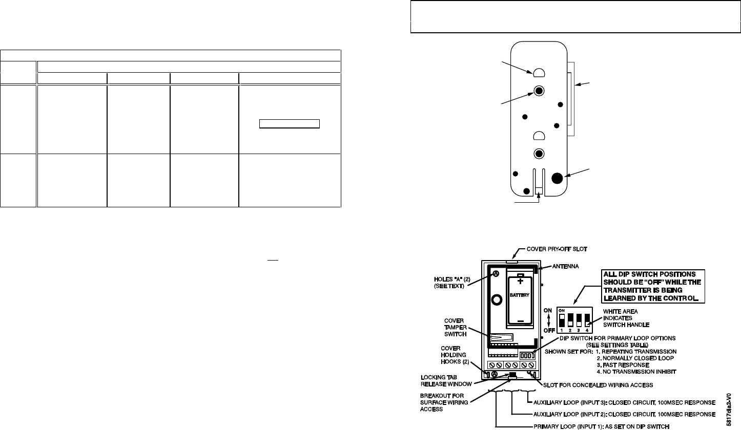
7 Set the DIP switch (after the control has enrolled the transmitter’s input IDs) for the desired
primary loop characteristics, as described in the table below.
P R I M A R Y L O O P O P T I O N S T A B L E
SWITCH
D I P S W I T C H P O S I T I O N
SETTING 1 2 3 4
ON
REPEATING
TRANSMISSION
(every 4 sec.)
UPON PRIMARY
LOOP FAULT
Use for high-priority
alarm, such as fire.
NORMALLY
OPEN CIRCUIT
PRIMARY LOOP
SLOW
PRIMARY LOOP
RESPONSE
(Approx. 200mSec
Normally Closed
Response Time)
3 MINUTE, ALL LOOP
TRANSMISSION INHIBIT
AFTER RESTORE OF
PRIMARY LOOP
See Note c.
This affects the Aux. loops as
well. Use on frequently used
doors, etc. to conserve battery.
OFF
SINGLE
TRANSMISSION
PER PRIMARY
LOOP
CHANGE-OF-
STATE
NORMALLY
CLOSED
CIRCUIT
PRIMARY
LOOP
FAST
PRIMARY LOOP
RESPONSE
(Approx. 5mSec
Normally Closed
Response Time)
NO
TRANSMISSION
INHIBIT
Notes: a. While the transmitter is being enrolled by the control, all DIP switch positions should
be OFF.
b. Except in the case of the position 4 ON setting, the Auxiliary loops are not affected by
the DIP switch settings.
c. For UL installations with fire zones, the position 4 ON setting must not
be used.
WIRING CONNECTIONS
With the battery still not inserted, connect the loop wiring to the unit’s terminals (see Diagram 2).
Note: If a contact loop is not to be used, no connection is needed across its terminals.
BATTERY INSTALLATION/REPLACEMENT
1. Remove the transmitter’s cover (if not already off) as described in Mounting Step 1.
2. Observe correct polarity and insert the battery provided into the battery holder (see
Diagram 2). Take care not to bend the antenna.
Note: Replace battery only with: Duracelll DL123A, Sanyo CR123A,
Panasonic CR123A, ADEMCO 466, or Varta CR123A.
CAUTION: Risk of fire, explosion, and burns. Do not recharge, disassemble, heat above
212°F (100°C), or incinerate. Dispose of used batteries promptly. Keep away
from children.
3. To replace the cover, engage the hooks along one edge and snap shut.
SPECIFICATIONS
Dimensions 1-9/16"W x 3-1/2"H x 1-3/16"D (40mm x 89mm x 30mm)
Battery 3V Lithium (see BATTERY INSTALLATION/REPLACEMENT).
TO THE INSTALLER
Regular maintenance and inspection (at least annually) by the installer and frequent testing by
the user are vital to continuous satisfactory operation of any alarm system.
The installer should assume the responsibility of developing and offering a regular maintenance
program to the user, as well as acquainting the user with the proper operation and limitations of
the alarm system and its component parts. Recommendations must be included for a specific
program of frequent testing (at least weekly) to ensure the system’s operation at all times.
REFER TO THE CONTROL'S INSTALLATION INSTRUCTIONS FOR THE
RECEIVER/CONTROL WITH WHICH THIS DEVICE IS USED, FOR DETAILS ON
LIMITATIONS OF THE ENTIRE ALARM SYSTEM.
CASE
HOLDING
POSTS (2)
PLATE
MOUNTING
HOLES (2)
ALIGNMENT GUIDE STRIP
(NOT USED IN THIS APPLICATION.
BREAK AWAY, IF DESIRED.)
CONCEALED WIRING
ENTRY HOLE
CASE LOCKING TAB
Diagram 1: MOUNTING PLATE
Diagram 2: 5817 (SHOWN WITH COVER REMOVED)