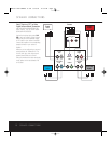
6 SUB-TS15 SUBWOOFER AMPLIFIER PANEL CONTROLS AND CONNECTIONS
SUB-TS15 SUBWOOFER AMPLIFIER PANEL CONTROLS AND CONNECTIONS
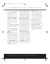
place itself in the Standby mode, depending on
whether it is receiving an audio signal.When
this switch is placed in the ON position, the
SUB-TS15 will remain on, whether or not it is
receiving an audio signal.
An LED located on top of the SUB-TS15
indicates whether the SUB-TS15 is in the
ON or STANDBY state when used with the
Audio-Sense On/Off Switch ¢ in the
AUTO position. The LED is lit blue to indi-
cate that the SUB-TS15 is receiving an
audio signal and is turned on, and the LED
is lit amber to indicate that no signal is
being received and the SUB-TS15 is in
Standby mode.
When the Audio-Sense On/Off Switch ¢
is in the ON position, the LED will be
lit blue, whether or not an audio signal is
present.
When the Master Power Switch ‚ is
turned off, the LED goes dark, no matter
which position the Audio-Sense On/Off
Switch ¢ is in.
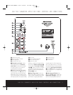
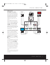
∞ Phase Switch: This switch determines
whether the SUB-TS15 subwoofer’s piston-
like action moves in and out in phase with
the main speakers. If the speakers were to
play out of phase, the sound waves pro-
duced by the subwoofer would be cancelled
out, reducing bass response. This phenome-
non depends in part on the relative place-
ment of the speakers in the room. In most
cases, the Phase Switch ∞ should be left
in the NORMAL position. However, it
does no harm to experiment with the Phase
Switch ∞, and you may leave it in the
position that maximizes bass response.
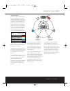
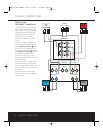
§ Line-Level Subwoofer (SUB) Input:
Connect the subwoofer output of a receiver
with digital surround sound decoding, such
as Dolby
®
Digital or DTS,
®
to this input. This
input bypasses the SUB-TS15’s internal
crossover circuitry, and should only be used
with a filtered signal. If your receiver does not
have digital decoding, you should use the
Line-Level Full-Range Inputs ¶ instead.
¶ Line-Level Full-Range Inputs: Connect
the line-level subwoofer output or preamp out-
put(s) of your receiver or amplifier to these
inputs. If your receiver does not have a sepa-
rate subwoofer output, use a Y-adapter (not
supplied) to bridge the receiver’s preamp out-
put to the main amp input for that channel,
and connect the long end of the adapter
to the corresponding line-level input on the
SUB-TS15. If your receiver has only a single
subwoofer output, you may connect it to
either the left or right line-level input on the
SUB-TS15, and no Y-adapter is needed.
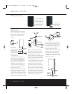
• Speaker-Level Outputs: If you are
using the Speaker-Level Inputs ª on the
SUB-TS15, you should connect these bind-
ing-post terminals to your front left and right
speakers, remembering to maintain polarity
by connecting the (+) terminal on the SUB-
TS15 subwoofer to the (+) terminal on the
speaker, and the (–) terminal on the SUB-
TS15 subwoofer to the (–) terminal on the
speaker. If you are not using the Speaker-
Level Inputs ª, then connect your front
left and right speakers directly to your receiver
or amplifier. See pages 9 through 12 for
further information on speaker connections.
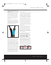
ª Speaker-Level Inputs: If your receiver
or amplifier does not have a line-level sub-
woofer output, connect these binding-post
terminals to the main left and right speaker
terminals of your receiver or amplifier.
Remember to maintain polarity by connecting
the (+) terminal on the receiver/amplifier to the
(+) terminal on the SUB-TS15 subwoofer, and
the (–) terminal on the receiver/amplifier to the
(–) terminal on the SUB-TS15 subwoofer.
‚ Master Power Switch: Place this
switch in the “•” position to power-on the
SUB-TS15 subwoofer. The SUB-TS15 will
then be either in the Standby mode or com-
pletely on, depending on the position of the
Audio-Sense On/Off Switch ¢.
⁄ AC Power Cord: Make sure to plug this
cord into an active, unswitched electrical out-
let for proper operation of the SUB-TS15.
The cord should not be plugged into the
accessory outlets found on some audio
components.
HKTS15-120V-omHKTS 15 OM 9/12/06 11:52 AM Page 6


