


harman/kardon Incorporated, 250 Crossways Park Dr. Woodbury, New York 11797 (516) 496-3400
harman/kardon Service Bulletin
Service bulletin # 9703 June 1997 This is considered a Major Repair
To: All harman/kardon Service Centers
Models: FL8300
Subject: Dead unit, no display; Service upgrade
In the event you receive an FL8300 that is dead, and upon inspection R701 is damaged or an otherwise
open circuit, perform the necessary steps listed below:
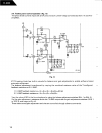
Due to current surges, early models of the FL8300 could repeatedly damage R701 (either a 1 ohm resistor or
1.5A micro fuse depending on version). Along with the replacement of R701, the positive lead should be
relocated on C125 to suppress any future current surges.
Additionally, two capacitors, now designated as C907 & C908, (1uf/50v) should be added to the power supply
output pins on regulator IC108 & IC111 on a unit serviced for any reason; these will add stability to help prevent
oscillation.
PROCEDURE:
1) Replace R701 with micro-fuse H/K # 5508722221, this component is on PCB7.
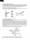
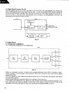
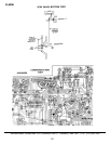
2) A PCB trace should be cut on the C125 (2200 uf/25v) positive lead on the main circuit board and an insulated
jumper wire attached from that lead to the junction of D109/110. Additionally another insulated jumper will
need to replace the trace that was cut. (see drawing)
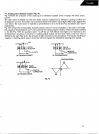
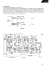
3) Add C907 & 908, 1uf/50v , H/K/ # 3479310971, one on each output pin to ground on regulators IC108 and
IC111. This is most easily accomplished by:
Soldering one 1uf cap to the jumpers 153 & 197. Observe polarity; J153 is ground.
Soldering one 1uf cap to the jumpers 185 & 186. Observe polarity; J186 is ground.
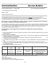
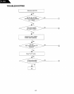
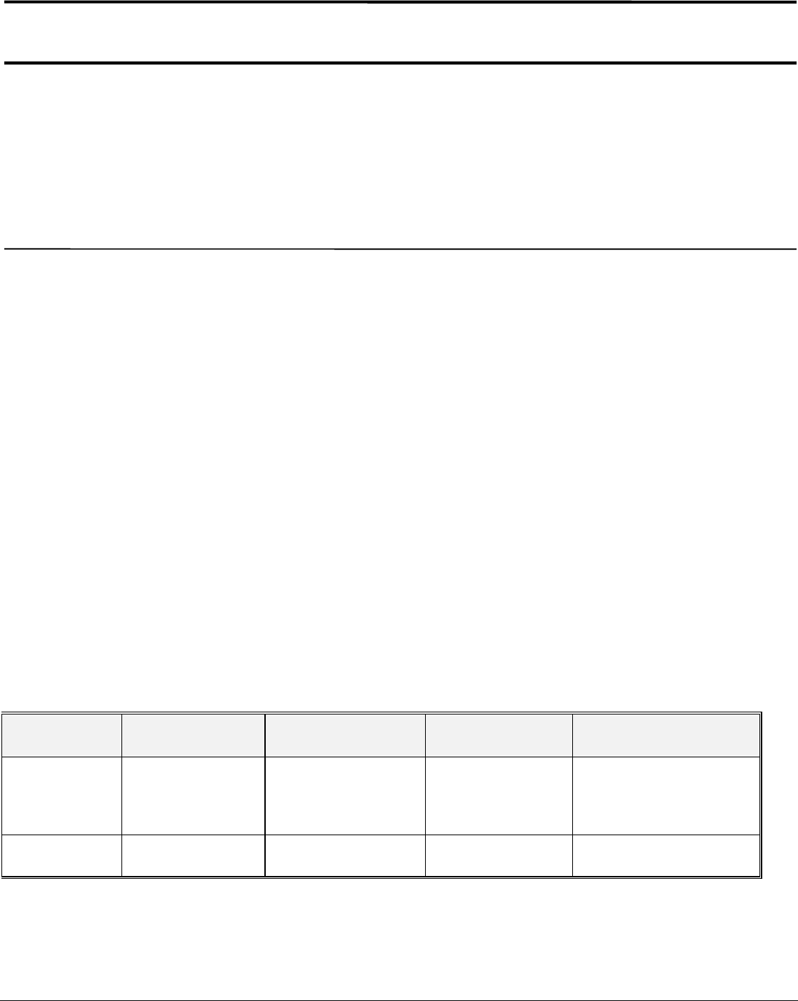
Model Serial number
120V
Serial number
230V
Action Correction
FL8300 IN0019-72213
and below
NOT REQUIRED R701 is damaged or
an open circuit
Replace R701,
re-route positive connection
on C125,
Add C907/908
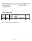
FL8300 IN0019-72214
and above
NOT REQUIRED Modified by factory NONE REQUIRED
24