


SPEAKER AND AUDIO CONNECTIONS
CD PLAYERAM AntennaFM Antenna
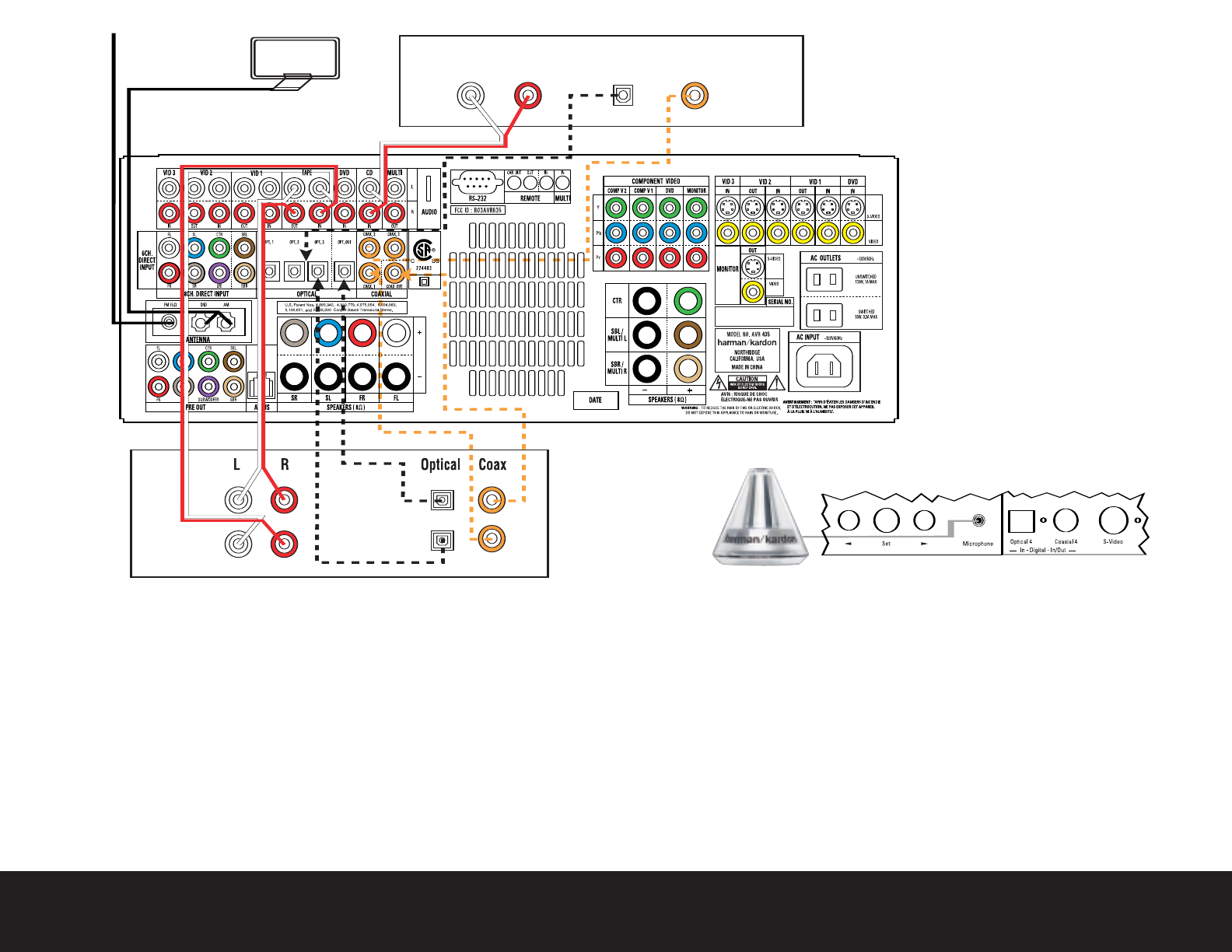
L R Optical Coax
REC/IN
PLAY/OUT
AUDIO RECORDER
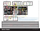
Step 4. Connect AM and FM antennas (Fig. 4) (see page 16).
Step 5. Connect source components, as shown in Figures 4 and 5, and
the Device Connection Options chart on the back of this guide (see
pages 16–17).
AUDIO connections: Right channel (red) on source to right (red)
on AVR, and left channel (
white) on source to left (white) on AVR.
DIGITAL AUDIO connections, if available: Choose either coaxial
(orange) to coaxial (orange) OR optical to optical for each device.
The Coaxial 1 input defaults to the DVD player;
however
, it may be
reassigned. Assign the other digital inputs and outputs as appropriate
for your equipment (see Step 7).
VIDEO connections: Choose component (Y/Pb/Pr – green/blue/
red), composite (yellow) or S-video (4-pin) for each video source.
The DVD Component Video inputs default to the DVD player, but may
be reassigned. Connect the component, composite and S-video
Monitor outputs to your Video Monitor (TV). Switch your TV set’s input
to match the type of video used for the currently selected source.
Step 6. Plug all components into AC power outlets.The outlets on the back of
the AVR 435 should be used
only for low-current products, such as
CD or DVD players, and the total should not exceed 100 watts.
Basic Receiver Configuration
Step 7. Select digital inputs: If your DVD is connected to Coaxial 1, no adjust-
ment is needed. For any other digital-device connections, use the
front-panel Digital Select button and the arrow buttons to select an
optical or coaxial digital input (see pages 21 and 35).
Step 8.
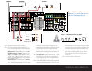
Plug the EzSet/EQ microphone into the Microphone Jack behind the
door on the front panel. Place the microphone at your preferred listen-
ing position and then follow the instructions on pages 23 to 26 of the
Owner’s Manual and the on-screen menus to run EzSet/EQ. Note that
you will hear a series of test tones and will then be instructed to move
the microphone and point it towards the three front speakers during
the second part of the calibration process.When the on-screen
menu indicates that EzSet/EQ is complete, your system settings for
speakers, delay times, channel output and room equalization are
entered into the unit’s memory. Unplug the microphone and keep
it for future use.
Step 9.
Your system is configured – sit back and enjoy.
Figure 4 – Audio Connections
Dashed lines (––––) indicate coaxial and optical
digital audio connections. Choose either type
(but not both) for each digital audio source.
Figure 5 – Connecting EzSet/EQ Microphone