


7
User Manual
2-Series
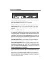
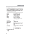
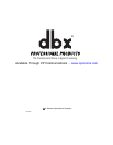
Operating Controls
Front Panels
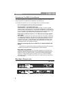
Input Gain Control: This control sets the signal level to the equalizer. It is capable of -
12dB to +12dB of gain. Its effect is apparent by viewing the OUTPUT LEVEL BAR GRAPH.
EQ Bypass: This switch removes the graphic equalizer section from the signal path.
The BYPASS switch does not, however, affect the INPUT GAIN, or LOW CUT filters.
EQ Bypass LED: This red LED lights when the EQ is in bypass mode. Note that
bypass mode only effects the graphic equalizer section of the 2 Series EQs. The
INPUT GAIN and and LOW CUT controls remain unaffected when the EQ is
bypassed.
Boost/Cut Range Selection Switch and LEDs: This switch selects which of the two
boost/cut ranges the equalizer will use, either ±6dB or ±12dB. The red LED lights
when the ±12dB range is selected.
Output Level Bar Graph: These four LEDs indicate output level of the equalizer.
The red LED is 3dB below clipping and is marked as +18dBu. It monitors the level at
the output of the equalizer after all other processing.
Clip LED: This LED lights whenever any internal signal level reaches 3dB below clip-
ping which may occur when any of the following happen: 1) the input signal is “hot-
ter” than +22dBu, 2) excessive gain is applied by the input gain control, or 3) exces-
sive boost is applied using the frequency sliders.
Frequency Band Slider Controls: Each one of these slider potentiometers will boost
or cut at its noted frequency by ±6dB or ±12dB, depending upon the position of the
BOOST/CUT RANGE switch. When all the sliders are in the center detented position
the output of the equalizer is flat. The frequency band centers of the 131 and 231 are
marked at 1/3rd of an octave intervals on ISO standard spacings, while the frequency
band centers of the 215 are marked at 2/3rds of an octave intervals on ISO standard
spacings.
Low Cut Enable Switch: The LOW-CUT switch inserts or removes the 18dB/octave
40Hz low-cut filter from the signal path. When the LOW-CUT switch is pushed in, the
LOW-CUT filter is IN the audio path.
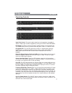
131- Single Channel 31 Band Graphic EQ
215- Dual Channel 15 Band Graphic EQ
231- Dual Channel 31 Band Graphic EQ