


The power-handling capability of any subwoofer
is related to both its ability to dissipate heat and
the maximum excursion limits of its cone. Once
the subwoofer’s voice coil moves outside the
magnetic gap, power can no longer be converted
into motion and all the amplifier’s power is con-
verted into heat. This is the most significant detri-
ment to subwoofer longevity, so overexcursion
should be avoided. Since cone excursion is differ-
ent for each type of enclosure, expect power han-
dling to be different for each enclosure as well.
EXCURSION IN A SEALED ENCLOSURE
Sealed enclosures exert the most control over
the motion of a subwoofer because the air inside
the box acts like a spring against the motion of the
subwoofer cone. Larger boxes allow for more
excursion, thus providing more low-frequency out-
put for the amount of power used. When a sub-
woofer is placed in a sealed box much larger than
its associated V
as
, it will perform as if it were in
an infinite-baffle installation. We do not recom-
mend this application.
EXCURSION IN A PORTED ENCLOSURE
Vented and bandpass enclosures have the lowest
amount of excursion for the amount of sound out-
put. This is a result of port output reinforcing the
sound output from the subwoofer. The mass of
the air contained in the port provides an acoustic
load on the subwoofer’s cone at the tuning fre-
quency, and this added mass decreases sub-
woofer-cone excursion. However, vented boxes
do not provide adequate subwoofer control when
driven below the tuned frequency (F
b
), so proper
design is important. A vented bandpass box will
have the lowest overall cone excursion, provided a
subsonic filter is used.
- 3 -
ENGLISH
OTHER CONSIDERATIONS
• Voice-coil overheating and burning due to
overexcursion are often caused by overdriving
an amplifier into “clipping.” A severely clipped
signal, or square wave, contains nearly twice
the power of a clean sine wave at the same
level. Bass that sounds broken up and distorted
at higher volumes is usually indicative of an
amplifier that is clipping and being asked to
deliver power beyond its ability.
• Infinite-baffle or “free-air” mounting applica-
tions allow for greater cone excursion than
subwoofers mounted in an enclosure. For this
application, power handling should be reduced
to half of its published specification.
• Study the excursion curves on the enclosed
Kappa Series data sheet and note the differ-
ences for different enclosure applications. The
type and size of box used will produce different
excursion demands on the subwoofer and, con-
sequently, different levels of power handling. As
long as the recommended enclosure parame-
ters are used, the subwoofer will perform prop-
erly in its enclosed environment. However, any
design deviation may result in less than opti-
mum performance, and may also subject the
subwoofer to overexcursion (i.e., where the
voice coil leaves the gap) that can eventually
damage the speaker. For additional help with
this issue, please contact your authorized
Infinity dealer.
IMPEDANCE CONSIDERATIONS
To achieve maximum amplifier output, you should
design a subwoofer system that provides
the lowest impedance that your amplifier can
drive safely. Here are some design tips:
• Don’t mix different subwoofer or enclosure
types in the same system. For example, use
only all single-voice coil woofers or all dual-
voice coil woofers.
• Connect a dual-voice coil subwoofer in series, but
NEVER connect separate subwoofers in series.
Because the amplifier’s damping factor (i.e., the
amplifier’s ability to control the motion of the sub-
woofer) is expressed as a ratio of
terminal impedance (i.e., the sum of speaker
impedance, wire resistance, and the direct-
current resistance of any crossover coil
connected to the subwoofer) to amplifier output
impedance, connecting subwoofers in series
reduces the damping factor of the amplifier to
a value less than one. Doing so may result in
poor system damping.
• You must use both coils of a dual-voice coil
subwoofer either in series or in parallel.
• Most amplifiers deliver exactly the same
amount of power bridged into a 4-ohm load as
they do running a 2-ohm stereo load.
POWER CONSIDERATIONS
To design a subwoofer system that maximizes
available amplifier power, keep the following rules
in mind:
• The formula for total system impedance of voice
coils connected in parallel is:
I = 1⁄(1⁄w
1
+ 1⁄w
2
+ 1⁄w
3
...)
where I is the total system impedance in ohms,
and w is the nominal impedance of a voice coil
in ohms.
• The formula for total system impedance of voice
coils connected in series is:
I = w
1
+ w
2
+ w
3
...
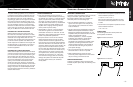
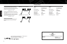
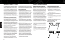
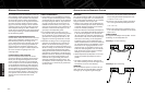
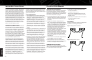
CONNECTIONS
The following illustrations show parallel and
series speaker connections.
Figure 1. Parallel connection
Figure 2. Series connection
POWER-HANDLING LIMITATIONS CONNECTING A SUBWOOFER SYSTEM