


7
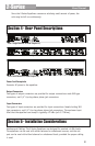
Section 2 - Operating Controls
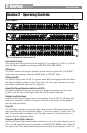
Front Panels
Input Gain Control
This control sets the signal level to the equalizer. It is capable of -12 dB to +12 dB of
gain. Its effect is apparent by viewing the OUTPUT LEVEL BAR GRAPH.
EQ Bypass
This switch removes the graphic equalizer section from the signal path. The BYPASS
switch does not, however, affect the INPUT GAIN, or LOW CUT filters.
EQ Bypass LED
This red LED lights when the EQ is in bypass mode. Note that bypass mode only effects
the graphic equalizer section of the 2 Series EQs. The input gain and and low cut con-
trols remain unaffected when the EQ is bypassed.
Boost/Cut Range Selection Switch and LEDs
Thisswitchselectswhichofthetwoboost/cutrangestheequalizerwilluse,either
±6dBor±12dB.TheredLEDlightswhenthe±12dBrangeisselected.
Output Level Bar Graph
These four LEDs indicate output level of the equalizer. The red LED is 3 dB below clip-
ping and is marked as +18 dBu. It monitors the level at the output of the equalizer
after all other processing.
Clip LED
This LED lights whenever any internal signal level reaches 3 dB below clipping which
may occur when any of the following happen: 1) the input signal is “hotter” than +18
dBu, 2) excessive gain is applied by the input gain control, or 3) excessive boost is
applied using the frequency sliders.
Frequency Band Slider Controls
Eachoneofthesesliderpotentiometerswillboostorcutatitsnotedfrequencyby±6
dBor±12dB,dependinguponthepositionoftheBOOST/CUTRANGEswitch.Whenall
the sliders are in the center detented position the output of the equalizer is flat. The
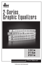
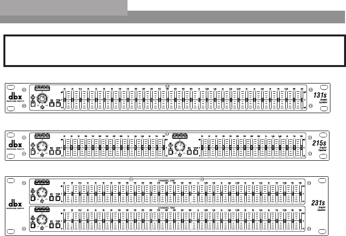
215s- Dual Channel 15 Band Graphic EQ
231s- Dual Channel 31 Band Graphic EQ
131s- Single Channel 31 Band Graphic EQ
User Manual
2-Series