


9
www.jbl.com
English
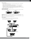
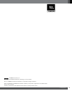
• Low-pass operation: The low-pass Crossover control setting you use for subwoofers will depend partly on the
settings you use for the system’s high-pass channels (see above) and partly on the type and location of your
system’s subwoofer. Start by setting the Crossover control to a frequency somewhat lower than the lowest
setting you used on any of the high-pass channels. After listening to music on the system for a time, fine-tune the
low-pass Crossover control setting to achieve a smooth transition from the subwoofer to the rest of the system’s
speakers while avoiding a “hole,” where the sounds that occur between the subwoofer and other speakers seem
to drop out. The illustration below shows the acceptable low-pass Crossover control frequency range.
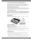
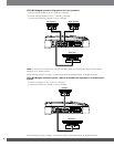
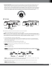
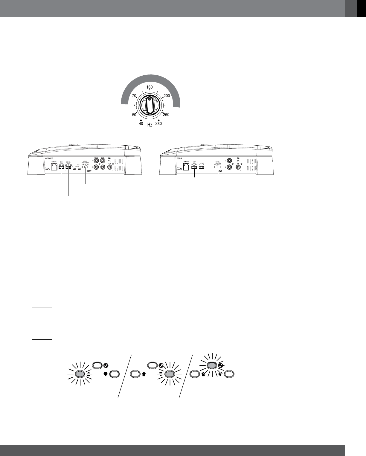
SET THE GAIN
EZ
Front/Rear
Input Level
Switch
Sub
Input Level
Switch
Gain LEDs
Switch
Gain LEDs
Switch
Input Level
Switch
GTO-3EZGTO-5EZ
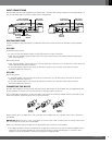
Before beginning, make sure the Gain LEDs switch is set to the “On” position.
1. Initially set all amplifier Input Level switches to the “Hi1” position.
NOTE: If you have connected the GTO-5EZ or GTO-3EZ amplifier to your factory audio system’s speaker outputs,
the audio system may show a “speaker disconnected” message, or may fail to play with an amplifier connected to its
output. If this happens, set the GTO amplifier’s Input Level switch to the “Hi2” position. The “Hi2” position includes a
circuit designed to fool this type of factory system into “seeing” a speaker connected to its output.
2. Turn all amplifier Gain controls to the “Min” setting.
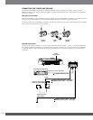
3. If you have connected an RBC Remote Bass Control (sold separately), set its knob to 3/4 (clockwise) before
performing the rest of the procedure. This will allow you to use the control to boost or attenuate the subwoofer
after you have completed setup.
4. Play the supplied setup CD through the vehicle’s audio system.
5. Set the audio system head unit’s volume to maximum (all the way up).
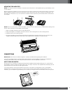
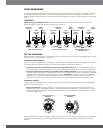
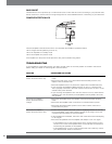
6. SLOWLY advance the Gain control setting. The Gain Indicator LEDs will light up:
• Yellow LED = Gain is too low
• Green LED = Gain is OK
• Red LED = Gain is too high
7. SLOWLY advance the Gain control so that the green Gain Indicator LED lights up. If you overshoot and the red
LED lights up, turn the Gain control down so that the yellow LED lights up and advance the Gain control SLOWLY
until the green LED lights up.
Gain too low
(increase gain)
Gain OKGain too high
(decrease gain)
NOTE: If you advance the Gain control all the way and the yellow LED is still lit up, turn the Gain control to “Min,”
switch the Input Level switch to the “Low” position and repeat Step 6.
8. Repeat Steps 5 and 6 for all of the amplifier channels. When all Gain Indicator LEDs are lit green, the GTO
amplifier gain setup is complete.
NOTE: Set the amplifier’s Gain LEDs switch to the “Off” position to prevent the red LEDs from lighting up
continually during normal operation.