


LOCATION
The TA1100 and TA1600 power transformer can generate a substantial magnetic field, so caution should be exercised in
the placement of low level components such as a tape deck, mixer or mic preamp to avoid inducing noise in the low level
circuitry. The amplifiers can also produce considerable heat in normal operation, so the primary consideration when deter-
mining a location for the amplifiers is to allow for adequate ventilation. The large heatsinks provide unrestricted airflow, but
care must be taken to keep the slots in the bottom panel and top cover clear. Use the rubber feet if the amplifier is placed
on a flat surface. If the amplifier is mounted in an equipment rack, make sure adjacent equipment does not impede cool air
flow.
We recommend leaving one rack space above and below the amplifier for proper cooling.
Inadequate ventilation can shorten component life, especially when other equipment raises the ambient air temperature, so
circulating fans should be considered in tight quarters.
AC LINE
The TA1100 and TA1600 operate from a 120 volt, 60Hz AC power line. Connection is made by a 16 gauge, IEC Type 320,
grounded line cord. For safety considerations only a properly grounded (earthed) receptacle should be used. If a grounded
circuit is not available do not break off the ground pin; use the proper adapter plug for a two wire receptacle. The line fuse
mounted on the rear panel will interrupt power to the amplifier if an internal fault is detected. If this fuse blows, replace it
with the same type and rating fuse only. The correct replacement fuse value is printed on the rear panel of the amplifier. If
the new fuse blows, this is an indication of a fault with the amplifier. Servicing should be performed only by a qualified
technician.
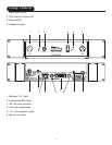
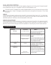
INPUT
The input jacks on the back of the amplifier will accept either
1
/
4
” balanced,
1
/
4
” unbalanced, or RCA unbalanced inputs. If
both jacks are used simultaneously, the
1
/
4
” input will automatically activate internal switches and disconnect the RCA
input, so that only the
1
/
4
” input remains operational.
OUTPUT
Speakers can be connected to the amplifier with
1
/
4
” mono plugs, or bare wires into spring clip connectors. Polarity of the
1
/
4
” connectors is Tip (+) and Sleeve (-).
HUM
It is not unusual to experience objectionable hum in even the simplest audio systems. If you are hearing hum in the
speakers or headphones, here is a very effective test that will help you troubleshoot your system, and eliminate the
problem:
CAUTION: DO NOT PERFORM THIS TEST WITH HEADPHONES . PROTECT YOUR EARS. MONITOR THE
OUTPUT OF YOUR AMPLIFIER AT A SAFE DISTANCE AWAY FROM FULL- RANGE SPEAKERS.
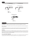
Hum Test:
Step 1:
Turn off the amplifier, turn both level controls all the way down, disconnect all input cables, disconnect head-
phones.
Step 2: Connect a full- range speaker to the output of One CHANNEL of the amplifier.
Step 3: Turn on amplifier. Slowly turn up the level controls and listen for hum. Turn level control back down and turn off
the amplifier. If the hum level was low, then the amplifier is not the source of the hum problem.
Step 4: Repeat this procedure on the remaining channel.
3
Installation