


processing circuitry prior to the MAQ-104 sufficient time to
stabilize before power is applied to the amplifiers. This
results in minimum turn-on/turn-off thump.
.
To program the turn-on delay period, set the relay dip
switches as shown below:
TIME
1
2
0.5 ON ON
1.0
ON OFF
2.0 OFF
ON
4.0 OFF OFF
FRONT/REAR DEFEAT SWITCHES
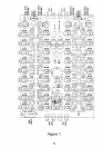
The switches in figure 1 are shown in the active position
(in the up position with the power connector on your upper
left.) By pushing the toggle down this defeats each respec-
tive front and rear channel.
FREQUENCY BAND BOOST AND CUT
On the MAQ-104 there are 10 bands of center frequency
boost and cut. By selecting a frequency noted on the PC
board you can boost or cut any band. Boost is ac-
complished by tuning the potentiometer clockwise. Cut is
done in reverse fashion counter clockwise. The flat posi-
tion is noted by a center detent on each potentiometer
INPUT LEVEL SENSITIVITY
The MAQ-104 is designed to be used at pre-amp and radio
output levels only (500 to 750 mVRMS). Higher input levels
to the MAQ-104 may overload the circuitry and must be
attenuated.
OUTPUT SENSITIVlTY ADJUSTMENT
There are four output gain adjustment potentiometers on
the MAQ-104. The output levels must be set in such a way
as to not overdrive the amplifiers.
A proper adjustment can be achieved by adjusting both the
source unit and MAQ-104 output levels. If you find that your
4