


– 17 –
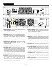
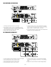
LEVEL CONTROLS
The gain for each channel can be controlled individually using the front panel level control. The controls have 32 detented
positions that are calibrated in dB. The maximum gain position is marked as the "0 dB" position, and the lower gain posi-
tions indicate the amount of attenuation relative to the maximum gain position in dB. Minimum gain position is marked as
“Off” and represents over 100dB of attenuation relative to the maximum gain position.
The CH B level control is used for all Bridged Mono configurations, and 100V and 70V modes (Except for GX2600 Dual
70V mode).
each channel. See diagrams
The Stereo/Biamp switch is defeated whenever the front panel Stereo/Mono switch is in the Mono position. In this case, the
Stereo/mono switch overrides the Stereo/Biamp switch, and the amplifier operates in mono mode.
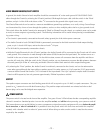
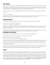
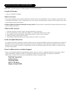
STEREO/BIAMP SWITCH
Turn amplifier off before operating this switch. This switch is located on the rear panel and selects either:
Stereo mode- 2 input signals and 2 output signals.
Biamp mode- 1 input signal and 2 output signals.
Biamp mode is useful if a mono signal needs to be distributed to speakers of differing impedance or power level. The load
switch for each channel can be selected for the appropriate load, and the level controls can be adjusted individually for
each channel. See diagrams
The Stereo/Biamp switch is defeated whenever the front panel Stereo/Mono switch is in the Mono position. In this case, the
Stereo/Mono switch overrides the Stereo/Biamp switch, and the amplifier operates in Mono mode.
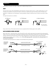
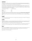
STEREO/MONO 70V 100V SWITCH
Turn amplifier off before operating this switch. This switch will override the Stereo/Biamp switch.
This Stereo/Mono 70V 100V switch is located on the front panel and selects either:
Stereo mode- 2 input signals and 2 output signals.
Mono, 70V, 100V mode- 1 input signal and 1 bridged output signal.
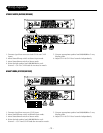
Mono mode uses the CH B input connector and level control only. The output load should be connected across the red ter-
minals of the output connectors. Set both load switches equal to 1/2 the load value. For example, after connecting a 4Ω
load across the red terminals, set both load switches to 2Ω. The rated power into the mono load will be double the rating
for a stereo load. See diagram
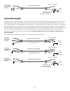
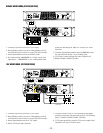
70V and 100V Mono mode also use the CH B input connector and level control only. The 70V or 100V speaker array load
should be connected across the red terminals of the output connectors. Set both load switches to the appropriate 70V or
100V value. The rated power into the mono load will be double the rating for a stereo load. See diagram
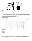
PROTECT
The red "Protect" LED on the front panel indicates that the NOMAD protection circuit has been activated, and is limiting
the output power of the amplifier. This indicates that during the “Protect” event, the NOMAD circuit detected a speaker
load that was temporarily significantly lower than the value selected with the load switch. Typically it may only occur when
a transient signal corresponds to a “dip” in the speakers’ impedance curve, and will not be objectionable. However, if the
nominal speaker impedance is significantly lower than the Load Switch setting, excessive clip limiting can result, accompa-
nied by continuous or prolonged illumination of the protect LED. In this situation the Load Switch should be changed to a
lower value until the “protect” events are eliminated, or occur infrequently. See “Load Switch” paragraph.