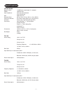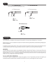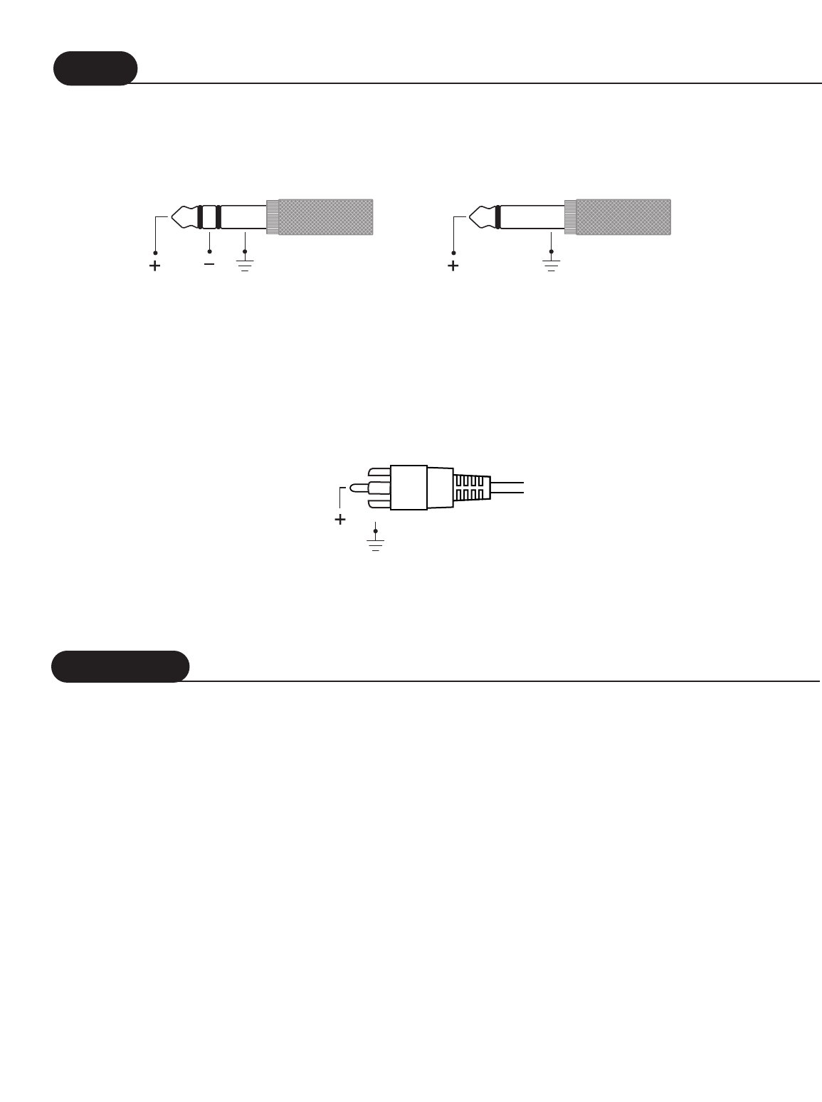
1/4" TRS Balanced Input
Check output of source unit for proper signal polarity
Tip = (+)
Ring = (–)
Sleeve = GND
1/4" TRS Unbalanced Input
Tip
= (+)
Sleeve = GND
4
Operation
Tip Ring Sleeve Tip Sleeve
1/4" TRS Unbalanced Input1/4" TRS Balanced Input
RCA Unbalanced Input
Tip = (+)
Shell = GND
Input
Tip
Shell
POWER SWITCH
The POWER switch is located on the front panel of the amplifier. An internal lamp indicates when it is turned on.
Standard practice is to turn the amplifier on last and off first when switching components to prevent sending damaging tran-
sients to the speakers.
It is possible to leave the power switch in the on position and switch the amplifier remotely through a power distribution block
or preamp switched outlet. When doing so make sure the switch is rated for the current required by the amplifier.
LEVEL SETUP
The input sensitivity for each channel can be adjusted individually using the Level Controls on the front panel. Set up the
amplifier Level Controls such that the amplifier clipping LED’s light occasionally when the source unit level control is turned
up approximately
2
/
3
to
3
/
4
full on.
Turning up the amplifier level controls any further than this will not make the amplifier any
louder! It will only increase the noise floor (hum and hiss)
TA 1100 - SHORT CIRCUIT PROTECTION
In the event of a short in the speaker load or cables, the protection circuit will automatically shut down the amplifier and
illuminate the red LED. When the short is removed, the red LED will turn off, and the signal will return to normal.


