Genesis Reference Amplifier Owners Manual Ver 2.0 6
Set-up and Operation
Speaker Connections
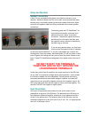
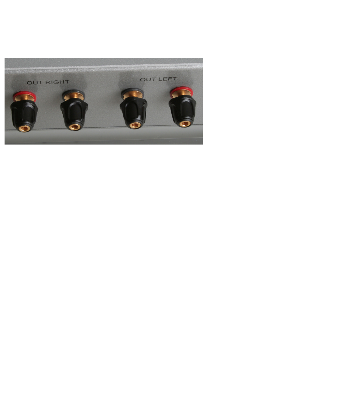
A pair of 5-way insulated binding posts is provided on the rear of your
amplifier. While this allows bare wire to be used, we recommend that firstly
banana plugs, or secondly spade lugs be used instead of bare wire. Make
sure that your speaker cables are firmly connected to the correct speaker
connections.
The binding posts are ETI CablePods™ for
improved signal transfer, enhanced sonic
performance, and a faster, more direct
connection. The positive (signal) terminal is
identified by the red ring on the base; and
the negative (return) terminal is identified by
the black ring on the base.
If you are using banana plugs, you may have
to remove the little plastic covers (if installed)
on the top of each CablePod™. If you are using spade lugs, unscrew the
binding posts, insert the spades, and hand tighten. Do not use pliers or other
tools to tighten the binding posts as you may strip the plastic threads on the
posts. These ETI CablePods are designed to fully tighten without the use of
tools.
DO NOT SHORT THE TERMINALS
TOGETHER AND DO NOT GROUND THE
LOUDSPEAKER TERMINALS
Unlike many other Class D amplifiers, the output terminals of the GR-Amp
do not “float” at a significant voltage above ground potential – which makes
the GR-Amp useable with all loudspeakers, including those with built-in
powered subwoofers and electrostatic designs. However, this does NOT
mean that you can ground the negative terminal of the speaker outputs. Do
NOT even attempt to short the two negative (return) terminals together. The
amplifier CAN NOT be bridged for higher power.
Input Connections
Use a pair of high-quality interconnects to hook up the output of your
preamplifier to the input of the GR-Amp. The balanced-input GR-Amp is a
fully balanced, differential amplifier, and hence, a true-balanced source is
crucial for top performance. The balanced input of the GR-Amp uses the
standard configuration for the XLR input of pin 2 “hot”. Pin 1 is signal ground,
and pin 3 is the signal “return”.


