


necessary to temporarily connect either of
the channels to this output.
Power up the system and set the DIP
switches 3 (SUM IN MODE) and 4 (LFE +10
dB) on the fi rst switch group to "ON" Now you
should hear an 85 Hz test signal from the
subwoofer and the main monitor connected
to the center channel output.
Toggle the -180° phase switch
(DIP 4 on the second switch
group) on and off, and set
it to the position which gives
the lowest sound level at the
listening position.
Next toggle the -90° phase
switch (DIP 3) on and off, and
again set it to the position which
gives the lowest sound level.
Finally, set the -180° phase switch
(DIP 4) to the opposite setting
and deactivate the test signal.
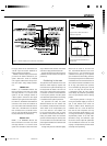
Phase correction method with
test equipment
The following procedure matches the phase
between the subwoofer and the main moni-
tors using a frequency analyser and a pink
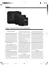
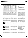
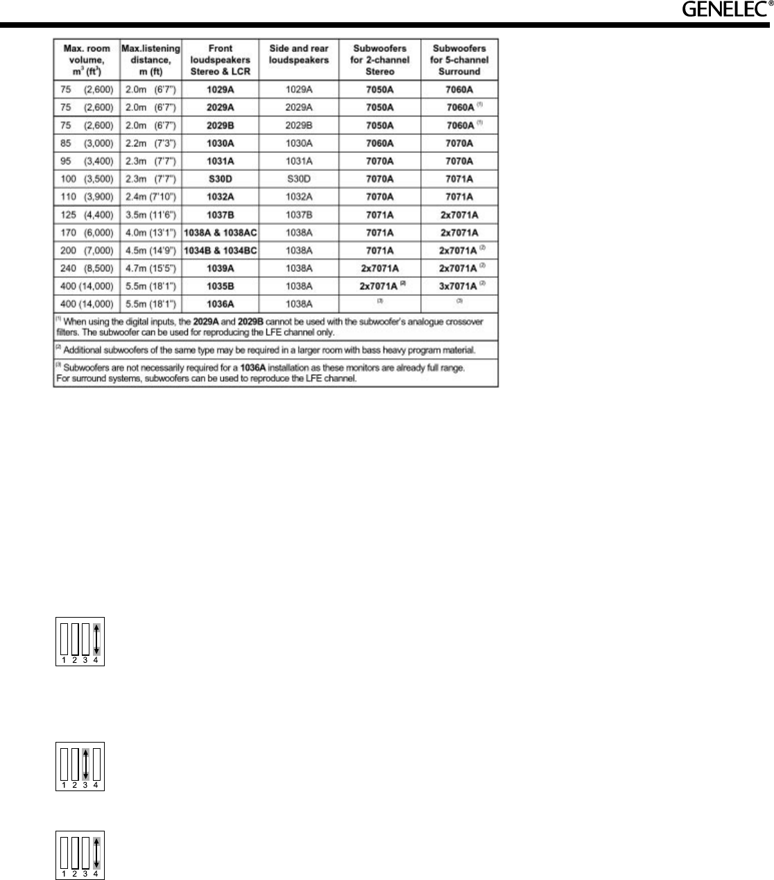
Table 2. Recommended subwoofer/main monitor combinations.
noise generator. Connect a high grade meas-
uring microphone to the analyser and feed
pink noise into the "CENTER IN" input of
the subwoofer. The subwoofer's bass man-
agement system will direct the frequencies
above 85 Hz to the center main monitor while
the subwoofer reproduces the frequencies
below 85 Hz.
Position the microphone at the listening
position and adjust the input sensitivity of
the subwoofer until frequencies below and
above 85 Hz are reproduced at equal level.
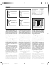
Then adjust the phase control switches for
the maximum dip of at least -6 dB at the
crossover frequency (85 Hz).
Change the -180° switch to the opposite
setting. The phase should now be set
correctly and the frequency analyser should
show a smooth response around 85 Hz.
Overload indicators
The mode indicator LED on the amplifi er
panel will turn from green to yellow to indi-
cate clipping and then to red to indicate that
the protection circuit has activated. If this
occurs frequently, reduce the input level to
the subwoofer until the LED remains green.
If the LED on the amplifi er panel is not
easily visible, the optional Remote LED Kit
can be used to bring it into view. The kit
consists of a LED in a compact case and
a RJ11 cable to connect the case and the
"REMOTE" RJ11 connector on the amplifi er
panel.
Subwoofer bypass control
A bypass control feature is included in the
subwoofer circuits so that the effect of the
subwoofer on the whole monitor system can
be determined. With the bypass switch on,
the high pass fi lters for the main monitors are
overridden and the system behaves as if the
subwoofer was not connected. The bypass
function has no effect on the LFE input. Two
different bypass remote controllers are avail-
able as optional equipment: 1092-400 switch
that can be connected to a 1/4" jack connec-
tor on the amplifi er panel and 7000-416 that
connects to the "REMOTE" RJ11 connector.
The 7000-416 option also includes remote
control of the "LFE +10 dB" function and a
link for the 7000-415 remote LED option.
Subwoofer in analogue matrix
surround sound systems.
When using Genelec 7060A, 7070A or 7171A
subwoofers in a consumer analogue matrix
surround sound system, such as Dolby Sur-
round, Dolby Pro-Logic or Pro-Logic II or a
professional matrix decoder such as a Dolby
SDU-4, route the front channels through the
subwoofer so that the output of the sub-
woofer is matched to the rest of the system
and select "Large" setting for the front speak-
ers on the decoder. If there is a subwoofer
channel output on the decoder it should NOT
be connected to the subwoofer's "LFE IN"
input since the processing within an ana-
logue decoder will confl ict with the fi ltering in
the subwoofer. Connecting the rear channels
to the subwoofer is optional since the rear
channels from most matrix decoders are
band limited down to 100 Hz.
Monitoring the LFE channel
in digital discrete surround
sound systems
Some digital surround sound systems use
a discrete Low Frequency Effects channel
which should be connected to the "LFE IN"
input on the amplifi er panel. This enables the
subwoofer to correctly reproduce all the bass
information in the mix.
Gen 7060A+7070A+7071A 22.5.2002, 11:045
Prosessimusta